- Joined
- 22 May 2020
- Messages
- 3
- Reaction score
- 0
- Country

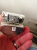
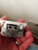
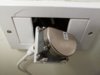
HI i just moved to a flat. The TV reception is sporadic at best and we have been needing to re-tune it every few days. I have tried to look online and all the sockets seem to be wired in and the live wire connected ? Does this look normal ? Any advice would be great thank you.