Neat Alarm Panel Wiring

Joined
8 Oct 2007
Messages
166
Reaction score
0
Country
United Kingdom
Any top tips to make the wiring inside the panel neat (been using Accenta G4 compact) ? I have wired a couple and haven't been satisfied with the outcome in terms of tidiness.

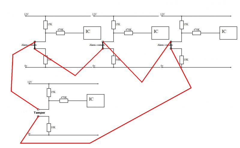
Main problem caused by having to use chock blocks to wire tamper circuit in series and to connect the multiple OV/12v for the sensors. These then float around, and by the time you put the battery in its all a bit of a squeeze.

Do you guys make these connections in a separate box ? Did think about using unused zone terminals (with links still across them) to link up the tampers, but is this seen as bad practice ?

Come to think of it I don't recall ever seeing the inside of a panel look anything other than a rats nest ! Is it just a fact that they don't lend themselves to neatness ?
 
Sponsored Links
you cant use any unused terminals as "spares" you may cause a short. You will if you put a tamper in a cct terminal. (it wont go bang, you just wont be able to set)

If you take your time you can make an alarm panel very neat, how ever doing so usualy involes tie wraps or some other retraint method which although looks nice cause grief when you have a fault to find, since you pull one cable they all move.
 
you cant use any unused terminals as "spares" you may cause a short. You will if you put a tamper in a cct terminal. (it wont go bang, you just wont be able to set)
.

They are already shorted as they are "normally closed" and have the staple links accross them !

For example, say zones 5-8 are unused and linked out, you could bring the output of zone 1 and the input to zone 2 tamper into zone 5 terminals, the output of zone 2 and the input of zone 3 tamper into zone 6 terminals etc. and not have to use choc block. Disadvantage is would need to undo if additions required in future, advantage is would confuse the hell out of someone else trying to work on the panel in future ! :LOL:
 
Don't think that would work tbh, even though the staples are in place they are still part of the circuit hence there are voltages aparrent on them. Connecting your tamper wires to them will either disable the tampers or create havoc with the alarm closed circuit voltages.
You need to keep the tampers separate.
 
Sponsored Links
Don't think that would work tbh, even though the staples are in place they are still part of the circuit hence there are voltages aparrent on them. Connecting your tamper wires to them will either disable the tampers or create havoc with the alarm closed circuit voltages.
You need to keep the tampers separate.

Surely the alarm terminals are purely a switch (normally closed) and no voltage is present ? In any case with a 0 ohm link accross them there aint much voltage !

But I agree its probably not the best idea.
 
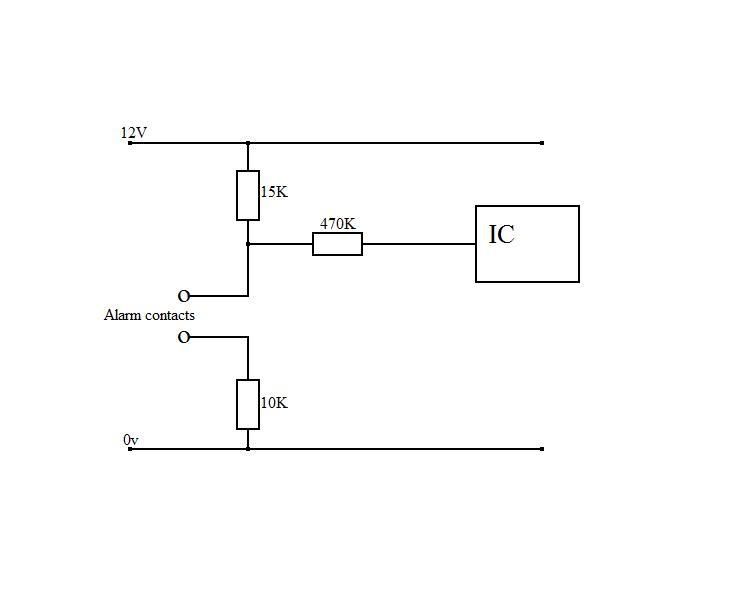
No, they are often stuck in the middle of a potential divider so there is some voltage there with reference to the zero volt rail, even with the link in.
What you are intending to do is short two parts of the alarm circuitry together, the alarm terminals and the tamper terminals.
This will either disable the tampers or cause the alarm circuits to not function correctly.
This is how a Texecom Veritas R8 alarm terminal is configured:
Alarmchannel.jpg

When the solid link is in the terminal link is held at 4.8v.
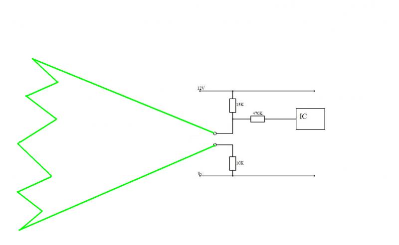
The only thing that should ever be connected to these terminals are dry alarm contacts, i.e. nothing with voltage on them.
 
Interesting stuff, thanks. But I still say that there will be no voltage difference measured across the alarm terminals with a link in place..
 
There wont be a difference across the terminals, but they are part of another circuit!!
You are intending on joining two circuits together which is wrong.
 
Interesting stuff, thanks. But I still say that there will be no voltage difference measured across the alarm terminals with a link in place..

sorry but you are not right at all. (with your reasoning) you are right about no difference on two linked termianls

a circuit and tamper have to be different polarity on a non resistor based panel.

so lets say the ccts are +ve and the tampers are -ve

lets now take a pair of circuit terminals.

one must be a + supply the other is looking for that +ve to say everything is ok.

you put a link across and all is well.

However if you connect the tamper loop to either terminal you now have + and -ve which cancel each other out, so there is no +ve coming into the 2nd cct terminal so the panel will not let you set (which is what i said in the first place)

Also by sending a voltage up a terminal that should not have one can also cause all or any "lower" circuits not to work at all.

(its worse with a panel that does have resisitors in the detection devices)
 
Best way to keep things neat is to twist all the pairs together from your individual cables together. This will sort the "birds nest" problem. Leaving too much/not enough slack on the cables will also cause problems. Trim all the cables to the same length. Most panels will have room behind the PCB to tuck any spares/terminal blocks behing, out of the way of the battery. You can usually get away without using terminal block for the auxilliary supplies, they should all fit in the terminal blocks on the PCB.

PS, your idea to utilise spare zones as terminal blocks is thoughtful, but incorrect. The problem being is that the actual zone circuits are at positive voltage in relation to the tamper circuit, which are at a negative voltage. Connect them together and you will get problems. Stick to proper terminal block.

Here's one I made earlier


you could move a whole family in that panel there is so much room
 
I agree they are not the most compact (not that I'm complaining)

They are designed to accomodate 2 x 17ah batteries! Hence the additional strengthening to the bottom of the panel.
 
Faced with a similar problem in a communications box I used crimp bootlaces ferrules to make the joint and a piece of heat shrink to insulate the exposed metal.

Use the type designed to take two wires as here

33131201.jpg
 
I agree they are not the most compact (not that I'm complaining)

They are designed to accomodate 2 x 17ah batteries! Hence the additional strengthening to the bottom of the panel.
Surely if you are installing a G3 system it must have the 17Ah battery not the 7Ah you are showing, wrong size battery - not G3
 

DIYnot Local

Staff member

If you need to find a tradesperson to get your job done, please try our local search below, or if you are doing it yourself you can find suppliers local to you.

Select the supplier or trade you require, enter your location to begin your search.


Are you a trade or supplier? You can create your listing free at DIYnot Local

 
Sponsored Links
Back
Top