New Socket Question, please

Joined
14 Aug 2006
Messages
29
Reaction score
0
Country
United Kingdom
Hi all,

Just a quick question, I'm adding in a new mains single socket to power a single adsl router (which uses a 12v DC type adaptor). It will only powering that item, and nothing else.

I have some 3 core 1.5mm flex cable which I was going to use and finish the job today, but wondering whether I should just get some 2.5mm twin and earth instead?

Is the 3 core 1.5mm flex (heat resistant, lol) a no no in this type of situation?

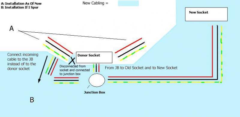
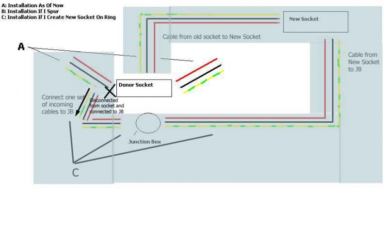
The socket giving power to the new one is a double socket with 2 sets of wires going into it, and I was going to basically add another set (i.e. for this new socket), or use a junction box to connect them all up.

Is that the correct way of doing it, or have I got it wrong (wouldn't be the first time!).

Thanks in advance
 
Sponsored Links
A big no no! Its one of those things; YOU may only want it for your router but if your not around and someone plugs in an electric fire, then what? Do the job right and use 2.5 mm three core cable using sleaving on the earth. If you have never spurred in an extra socket find a friend locally to advise or show you what to do or get a tradesman in.
 
Avoid using junction boxes and wire straight into the socket (with 2.5mm). You also need to prove that the existing socket is part of a ring and not a spur.
 
A big no no! Its one of those things; YOU may only want it for your router but if your not around and someone plugs in an electric fire, then what? Do the job right and use 2.5 mm three core cable using sleaving on the earth. If you have never spurred in an extra socket find a friend locally to advise or show you what to do or get a tradesman in.

Thanks for the reply. I thought as much, it was just being lazy and wanting to finish the job today. Not much of today left now so I'll leave it till tomorrow lol.

With regards to adding the extra spur, a friend who is an electrician said it was possible to add the extra socket using a junction box. I've done an array of electrical work here and there, but never a spurred socket. Does his advice sound ok? (it should be, for what he charges!).
 
Sponsored Links
Avoid using junction boxes and wire straight into the socket (with 2.5mm). You also need to prove that the existing socket is part of a ring and not a spur.

Thanks for the reply. How would I go about confirming whether it is not a spur? Do I need to test with a measuring device (I have a one but not sure if I have the talent to try this out lol!)?

I may just get my friend to do this for me, but am definitely interested in learning how to do it anyway. Will come in handy later on I'm sure.

Thanks again for the replies.
 
if your not around and someone plugs in an electric fire, then what?
Then it will work fine - 13A is perfectly OK for 1.5mm² unless it's completely buried in thermal insulation.

What may not be fine, and I can't be @rsed to do the calculation, is 1.5mm² on a B32 from a fault protection POV....


Do the job right and use 2.5 mm three core cable using sleaving on the earth.
Absolutely - no reason whatsoever not to.

With regards to adding the extra spur, a friend who is an electrician said it was possible to add the extra socket using a junction box. I've done an array of electrical work here and there, but never a spurred socket. Does his advice sound ok? (it should be, for what he charges!).
You can use a JB if you have to, but it should remain accessible for inspection in the future. Better to spur directly from the socket if you can.

Better still to extend the ring to the new socket.
 
Thanks for the reply. How would I go about confirming whether it is not a spur? Do I need to test with a measuring device (I have a one but not sure if I have the talent to try this out lol!)?
What sort of "measuring device" do you have?


I may just get my friend to do this for me, but am definitely interested in learning how to do it anyway. Will come in handy later on I'm sure.
If he's happy to do that then go for it, and watch and learn...
 
Thanks for the reply. How would I go about confirming whether it is not a spur? Do I need to test with a measuring device (I have a one but not sure if I have the talent to try this out lol!)?
What sort of "measuring device" do you have?

It has a plethora of settings and measures voltage/amperage etc. It cost £130 and was useful when fixing some electrical problems with a friend's car! lol. It may/may not be appropriate but I'm sure I could access one that is, if I knew exactly what type was required.


I may just get my friend to do this for me, but am definitely interested in learning how to do it anyway. Will come in handy later on I'm sure.
If he's happy to do that then go for it, and watch and learn...[/quote]

I think that's probably the best option, but I very much appreciate the replies. I think I'll pull the cabling through with the 2.5mm twin and earth and let him do the connections when he's ready.

Thanks again for all your help.
 
Is this work in a domestic or commercial premisis?

It's domestic.

I've been reading a bit and having failed to entice the electrician round today, I thought I might give this a shot myself.

I've concluded it is a ring main as I've tested by removing a socket from the wall. It had two sets of wires going into it. I removed and tested it with the multimeter saying there was no resistance.

What I was thinking of doing was to either 1) create a spur from a donor socket nearby that has 2 sets of wires (so this should be ok to spur from?) or 2) create a new socket in the ring by disconnecting one set of wires from the donor socket and have them connected to the second set of wires that will be connected to the new socket.

First off, is 2 feasible and the correct way of going about doing that? Is it preferable to just creating a spur (why create extra work for myself etc)?

Further, I was going to use a junction box, which would be located approximately two inches below the donor socket within a plasterboard wall, and screwed to the baton. It will still be accessible once the donor socket backbox is removed (it can be unscrewed and lifted outwards of the socket hole and worked on there).

I was going to use it for creating either the spur or the new socket on the ring. In the case of the spur it would house one connection from the donor coming in, with two connections coming out: 1 to the spur one to the donor. In the case of the new socket on ring it would house the return from the new socket and the old wire that was removed from the donor (i.e. it would just act as a connector between them).

The reason I preferred the junction box is that the wires are quite thick and it seems tricky to get all three in without them coming loose or breaking, and the backbox seems pretty cosy as it is!

I can upload a diagram if it would help?

Also, if I wanted to create spurs for tv power (i.e. attach the TVs directly to the fused spur socket) would that be ok?

Thanks in advance for any advice.
 
I've concluded it is a ring main as I've tested by removing a socket from the wall. It had two sets of wires going into it. I removed and tested it with the multimeter saying there was no resistance.
No resistance between which points?


What I was thinking of doing was to either 1) create a spur from a donor socket nearby that has 2 sets of wires (so this should be ok to spur from?)
Not necessarily - with a ring final circuit there's no guarantee that a socket with 2 cables isn't a spur with another spur from it.


or 2) create a new socket in the ring by disconnecting one set of wires from the donor socket and have them connected to the second set of wires that will be connected to the new socket.
Don't forget you then need to connect the new socket back to the one from which you removed the cable.

First off, is 2 feasible and the correct way of going about doing that? Is it preferable to just creating a spur (why create extra work for myself etc)?
It's preferable to maintain the ring.


Further, I was going to use a junction box, which would be located approximately two inches below the donor socket within a plasterboard wall, and screwed to the baton. It will still be accessible once the donor socket backbox is removed (it can be unscrewed and lifted outwards of the socket hole and worked on there).
And it's preferable to avoid joining cables if you can.


I was going to use it for creating either the spur or the new socket on the ring. In the case of the spur it would house one connection from the donor coming in, with two connections coming out: 1 to the spur one to the donor. In the case of the new socket on ring it would house the return from the new socket and the old wire that was removed from the donor (i.e. it would just act as a connector between them).
Can't get my head round that - maybe it's just late...


I can upload a diagram if it would help?
Yes please.


Also, if I wanted to create spurs for tv power (i.e. attach the TVs directly to the fused spur socket) would that be ok?
You can have what you like on the load side of a fused spur - you can't add one supplied from a spurred socket which is unfused.

And if you're installing FCUs it's better to put them directly onto the ring if you can.
 
Thank you very much for the reply. In answer to your points:

No resistance between which points?

I tested by taking both red wires off and attaching both to both the connectors on the multimeter.


Not necessarily - with a ring final circuit there's no guarantee that a socket with 2 cables isn't a spur with another spur from it.

Ah. I was under the impression that if the continuity test confirmed the socket (donor) was part of a ring, it could not be a spur? How can I test if the donor socket is really a spur (with a spur attached, which I thought was a no no).


Don't forget you then need to connect the new socket back to the one from which you removed the cable.

Thats what I refer to when I mention the junction box acting as simply the connector between the wiring back from the new ring socket and connecting to the wire removed from the donor socket.

It's preferable to maintain the ring.
Great, thanks. Would it be too much to ask the reason why? I understand if you think it would be way over my head/too much to explain on here! Edit:ignore that, I sort of understand the reason why. Something to do with the wires being able to be thinner due to the load being split. One question though, simply out of interest: what is the difference between single phase and three phase circuits?


And it's preferable to avoid joining cables if you can.
Ok cool. However, how can I then connect the return wire from the new socket to the removed wire from the donor socket?


Can't get my head round that - maybe it's just late...
lol. I'm sure my explanation is probably crap. What I meant is probably best described by a diagram, but in short, the junction box would act as either connector (as explained above) or as splice (is that the correct term) for the spur.


Yes please.
Will do. Will get one up in about 2 mins. Please forgive it's crudeness though, as it'll be done in paint or similar!!!


You can have what you like on the load side of a fused spur - you can't add one supplied from a spurred socket which is unfused.

And if you're installing FCUs it's better to put them directly onto the ring if you can.

Understood, thanks!
 
Ok. Got some images up. Have checked them for accuracy and they seem ok. But, as you've mentioned, it's kinda late!

First image is here:


This represents the changes if I spur.

Second image is here:


This represents the changes if I create a new socket.

I hope they make sense.[/img]
 

DIYnot Local

Staff member

If you need to find a tradesperson to get your job done, please try our local search below, or if you are doing it yourself you can find suppliers local to you.

Select the supplier or trade you require, enter your location to begin your search.


Are you a trade or supplier? You can create your listing free at DIYnot Local

 
Sponsored Links
Back
Top