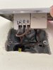
Again photos of that switch
So its important to work out the 3 wires & Earth which main cable they go to behind the box if at all possible - you can not mix them up
Brown/Black/Grey/Earth - needs to be the same set - so will all be covered in another outer insulation.
Are you at least able to workout which SET is which ?
OR are you 100% that the 3 wires say into the bottom are from the same main cable ? OR the TOP 3 are the same cable
I have uploaded 2 pics.
The NonWorkingK2 image is a picture of the switch which is not working and has the wire sleeves behind the backbox. I can't pull the wire sleeves out but peering very closely, I see that the top 3 wires are coming from the same sleeve. So I assume the other 3 wires are coming from another sleeve.
I had wired the same top 3 wires into the same module/gang on the switch.
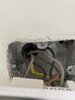
It was the other 3 wires that were showing some continuity and not the top 3 wires.
Now have a look at the other switch (WorkingK1 image).
I have separated all the wires.
There are 4 sets of wires (from 4 outer insulations).
I have separated them according to which sleeve they come from.
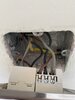
The set which I have used to connect to the switch only has 2 wires from that sleeve.
Using my Multimeter, I found that there are 2 live wires in total which I have indicated.
All the other wires don't show any voltage except the Switched Live one which I have connected (while the switch is turned on).
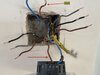
I hope this gives some clarity on the setup.
JH