No Voltage on Wires in Light Switch

Status
Not open for further replies.
you have both cores 2 & 3 Core
If you ONLY have 2 switches that control 1 load - like a light - then its
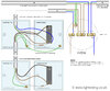
2 way switch (3 wire system, new harmonised cable colours)

you can see the wiring diagram here , on the LINK
And you should be able to MATCH that to the wires you have in each switch -
BUT its only showing for 1 circuit - so 2 switches controlling 1 light

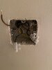
Remember in your setup you HAVE 2 GANGS - 2 switches - so you have the circuit twice - BUT the are completely seperate - so just focus on the one 3 core cable - and its associated 2 core cable - for 1
circuit

hope that helps
 

Attachments

  • two-way-switching-wiring-diagram.jpg
    two-way-switching-wiring-diagram.jpg
    153.7 KB · Views: 40
Sponsored Links
So to clarify, on the working switch where I have 2 x 3core and 2 x 2core, the 2 core wires are connected to the two sets of lights I have on the ceiling, while the 3 core wires run to the other 2-way switch.
Is that correct?

Since I have two sets of lights on the ceiling (hence the 2-gang switches), does this mean I have 2 loads?

JH
 
yes, as far as i can make out with your posts
And they would also be paired - 2 core with a 3 core - so you should know which 2 core was in the same terminals as the 3 core on the switch

Two separate circuits - 2 loads
 
OK, so next, you said:
BUT now you have them all disconnected - with the power off
you should be able to TEST the 3 core cable - as that SHOULD just be one bit of cable between each switch
now you have a multimeter - you can set on continuity ohms and test to see if a cable is broken

On my MM, it shows 20k, 2k and 200.
Which setting do I use?
Do I test with one probe on earth and the other touching each of the wires in turn?
What should I want to see on the readout?

JH
 
Sponsored Links
NOT WITH THE POWER ON
This is a continuity TEST

you could use the earth as a connector - BUT i suggested you just test the 3 cables themselves

the multimeter should be on 200 - lowest setting - and touch the probes together - you should get a zero reading , even on the other settings, it will still be zero - no resistance

NOW what are you are trying to do - is see if there is a continuous piece of wire and that it has not broken, which the reading of zero will tellyou.

If you put a probe on the 3 core BLACK and a probe on the same 3 core grey - then that signal will say go down the grey wire to the other switch - if you join at the other switch the grey to the black then the signal can come all the way back to the other probe on the multimeter - and complete the circuit and give a reading on the multimeter - it will not be zero - because those wires have a little bit of resistance across the length - BUT you will either get close to zero or no reading
 
Ok, with the power off, I touched both probes to the same wire, one at a time.
Every single one showed some type of reading but that dwindled down to close to zero.
However, one set of wires (Black, Grey and Brown) showed erratic readings and although it came down towards zero it jumped up again and started dancing.
Same thing on the other side with one set of wires.

So now, what does that tell me?

JH
 
can you explain what you did -
I touched both probes to the same wire, one at a time.
not sure what you are doing exactly
BOTH PROBES SHOULD NOT be on same wire

a poor connection will flick around
so you do need to make sure the contacts are good

Try again and NOTE what you are doing back here and the readings
not sure Dwindling - or the multimeter you are using
if you just Hold the probes together and do you get a solid non moving reading on the meter - JUST to make sure the meter is good
 
Last edited:
can you explain what you did -
not sure what you are doing exactly
BOTH PROBES SHOULD NOT be on same wire

That means I misunderstood. I've been touching both probes to the same wire, one at a time.
If this is wrong, where should I be touching the other probe? To earth?

JH
 
Wrong
NOW what are you are trying to do - is see if there is a continuous piece of wire and that it has not broken, which the reading of zero will tellyou.

If you put a probe on the 3 core BLACK and a probe on the same 3 core grey - then that signal will say go down the grey wire to the other switch - if you join at the other switch the grey to the black then the signal can come all the way back to the other probe on the multimeter - and complete the circuit and give a reading on the multimeter - it will not be zero - because those wires have a little bit of resistance across the length - BUT you will either get close to zero or no reading

That means I misunderstood. I've been touching both probes to the same wire, one at a time.
IF the two probes are on the same bit of copper - should be 100% ZERO
and no change - BUT Thats not what i suggested
 
There are two sets of wires on the other switch. How do I know which set to join together?
Trial and error?
 
See image. I connected the black and grey on each set with each other in a connector block.

On the other switch, I touched one probe to black and the other to grey.
I did it for both sets.
The reading did not even register. It stayed at 1, which seems to be default.

JH
 

Attachments

  • 08715609-31FA-48EA-BABC-CA445C623D09.jpeg
    08715609-31FA-48EA-BABC-CA445C623D09.jpeg
    284.6 KB · Views: 47
OK - so now those are shorted out
at the other end - the meter with a probe on grey and a probe on black should read zero

MOD: Apologies, this thread has dragged on long enough. The OP comes across as a potential danger to themselves and others in the household. PLEASE ENGAGE THE SERVICES OF A QUALIFIED ELECTRICIAN.
 

Attachments

  • Wiring.pdf
    393.6 KB · Views: 68
Last edited by a moderator:

DIYnot Local

Staff member

If you need to find a tradesperson to get your job done, please try our local search below, or if you are doing it yourself you can find suppliers local to you.

Select the supplier or trade you require, enter your location to begin your search.


Are you a trade or supplier? You can create your listing free at DIYnot Local

 
Status
Not open for further replies.
Sponsored Links
Back
Top