http://media.diynot.com/121000_120756_94609_21610927_thumb.jpg
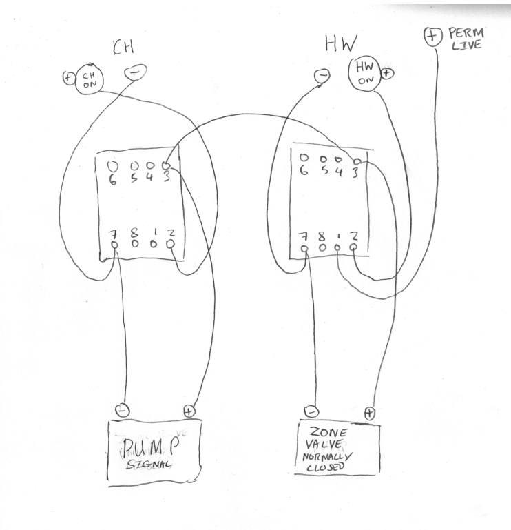
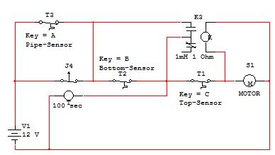
Please excuse my complete lack of protocol in this diagram. What this does is as follows:
CH and HW at the top refer to 240V outputs from my heating programmer. The CH and HW outputs go through relay switches which are connected to a zone valve which controls hot water coming in to the building and a pump signal which switches the export pump pumping that hot water on and off. The relays work in such a way that if either the HW or the CH (or both) are calling for heat the zone valve will open and the export pump will come on. It all works well. But...
I now want to add an extra condition to this setup. Basically, there is a buffer tank in the house which stores up hot water. It will charge up with a charge pump using excess heat when the VZ is open and the export pump is on, and then, when it is fully charged the charge pump will switch off and I want it the ZV to close and the export pump to switch off. The heat from the buffer tank will then be used up by circulating that water with separate circulating pumps (not show here for simplicity and controlled by the heating programmer). Once the buffer tank is fully discharged I want the zone valve to open and the export pump to re-start.
I'm happy wiring the buffer tank charging pump to stats at the top and bottom of the tank to switch the charging on and off. I am unsure though of how to wire this into the relay setup. I think I may need another relay switch?
ZV and export pump:
Opens / switches on when CH or HW calling for heat and top buffer tank stat is below temp
Closes / switches off when bottom buffer tank reaches required temp
Charge pump:
Comes on if ZV open and export pump is on
Switches off if bottom buffer tank stat reaches required temp.
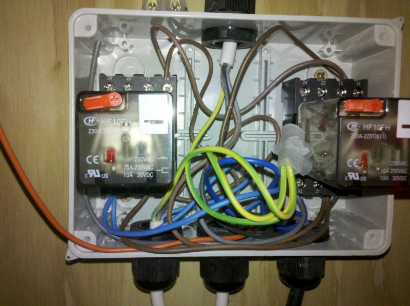
Below is a picture of my relay switches:
http://media.diynot.com/121000_120756_94611_11336986_thumb.jpg
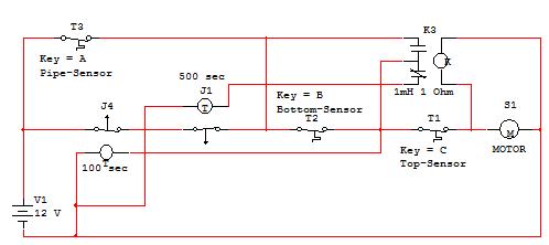
Please excuse my complete lack of protocol in this diagram. What this does is as follows:
CH and HW at the top refer to 240V outputs from my heating programmer. The CH and HW outputs go through relay switches which are connected to a zone valve which controls hot water coming in to the building and a pump signal which switches the export pump pumping that hot water on and off. The relays work in such a way that if either the HW or the CH (or both) are calling for heat the zone valve will open and the export pump will come on. It all works well. But...
I now want to add an extra condition to this setup. Basically, there is a buffer tank in the house which stores up hot water. It will charge up with a charge pump using excess heat when the VZ is open and the export pump is on, and then, when it is fully charged the charge pump will switch off and I want it the ZV to close and the export pump to switch off. The heat from the buffer tank will then be used up by circulating that water with separate circulating pumps (not show here for simplicity and controlled by the heating programmer). Once the buffer tank is fully discharged I want the zone valve to open and the export pump to re-start.
I'm happy wiring the buffer tank charging pump to stats at the top and bottom of the tank to switch the charging on and off. I am unsure though of how to wire this into the relay setup. I think I may need another relay switch?
ZV and export pump:
Opens / switches on when CH or HW calling for heat and top buffer tank stat is below temp
Closes / switches off when bottom buffer tank reaches required temp
Charge pump:
Comes on if ZV open and export pump is on
Switches off if bottom buffer tank stat reaches required temp.
Below is a picture of my relay switches:
http://media.diynot.com/121000_120756_94611_11336986_thumb.jpg