Replacing 2 Switch for four lights - wiring confusion

Joined
20 Nov 2015
Messages
7
Reaction score
0
Country
United Kingdom
Hi all,

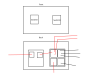
I've wanted to replace a bunch of switch in my house with dimmers. Most of the wiring in the house was quickly sorted however my living room one has left me puzzled. It was ten wires (4 red, 4 black, 2 earthed in the metal plate) . It’s not set-up to be 2 way (or at least there isn’t a second switch anywhere) so I’m not sure how I’m to wire this up into my new switch. I’ve drawn the current wiring up below. Hopefully you can help. Annoyingly none of it appears labelled nor are the connectors on the switch

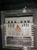
Switch 1: The left one with a single in/out red wire controls two ceiling lights
Switch 2: The right one controls two wall lights
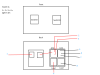
 

Attachments

  • Switch.png
    Switch.png
    10.7 KB · Views: 141
Sponsored Links
Looking at the drawing of the switch on the right, you have depicted 4 terminals.

Does that mean the switch is a 4 terminal one with two terminals top and two bottom (like you have drawn), or are any of those 4 boxes depicting terminal blocks where the wires are joined to each other but not to the switch?
 
There are four terminals on the right side which are connect to one big plastic terminal behind the right switch so I assume it's all connected

After a bit more experimentation I have some more info in the updated diagram. Not sure if the wording on the right terminal is correct but thats just what's on the plastic.
 

Attachments

  • Switch.png
    Switch.png
    13.2 KB · Views: 150
Sponsored Links
Here you go!
 

Attachments

  • IMG_20151120_180929.jpg
    IMG_20151120_180929.jpg
    73.4 KB · Views: 148
  • IMG_20151120_181457.jpg
    IMG_20151120_181457.jpg
    71.7 KB · Views: 128
  • IMG_20151120_181520.jpg
    IMG_20151120_181520.jpg
    71.3 KB · Views: 138
OK. What is marked (if anything) adjacent to each of those 4 terminals on that switch?
 
That switch with the 4 connections?

Does it just switch two wall fittings?

On and off with the one switch?
 
Ok, thanks.

I see 20A on the switch which (likely) means it is a double pole switch.


You will have to connect ALL the blacks in a separate connector block and position safely in the back box.
Then replicate the reds in the four terminals of your new switches.

Also, if the new one is metal connect the earth terminal to the back box.
 
The terminal with three reds in is live loop.

The terminal with three blacks is neutral in (two from the loop and one from the outgoing switched supply on the other switch).

The other two are live and neutral out to the wall lights.
 
Thanks for the help everyone. Because I'm a beginner, here's what I'm trying to replace it with. Is this even possible with this configuration?
 

Attachments

  • IMG_20151120_191852.jpg
    IMG_20151120_191852.jpg
    86 KB · Views: 126
So all black are connecting together separately in a connector block as per your previous comment. Leaving me with four red left, yet if all three go into a signal L in the new box that leaves me with another L and two 'X's left. Any chance you could draw me a diagram. Apologies.
 
Just use your diagram, but put all of the blacks into a connector.

From your diagram

On the right hand switch, the top reds into L (and using the little piece, link to the L on the other switch), the other one into the squiggly x
On the left hand switch, the left terminal is the L, and the right is the X
 

DIYnot Local

Staff member

If you need to find a tradesperson to get your job done, please try our local search below, or if you are doing it yourself you can find suppliers local to you.

Select the supplier or trade you require, enter your location to begin your search.


Are you a trade or supplier? You can create your listing free at DIYnot Local

 
Sponsored Links
Back
Top