

I want to replace the pull cord light switch in my bathroom because it is noisy.
When the light switch is turned on, it also turns on the extractor fan. When it is turned off the fan continues for a set time then turns off.
The circuitry also has a fan isolator switch.
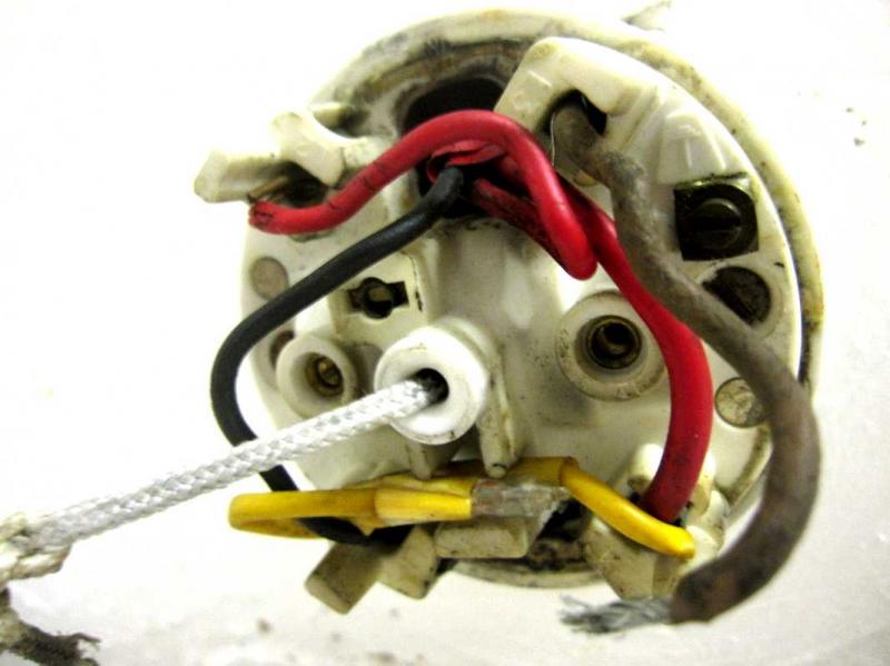
The Old Switch has 4 connections; L1, L2, L3 and L4 plus an earth. The wiring going into the Old Switch is as follows:
Black into L1
Red into L2
Wire with red sleeve into L4
It also has a yellow wire with a light connecting L2 to L4. When the bathroom light is off the light within the switch is on.
Their is a short brown wire only within the switch casing connected to L3 but the other end is connected to nothing. Maybe it came loose when I opened the casing. The circuitry still works with this short brown cable loose.
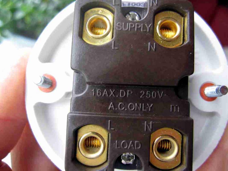
The new switch has the following connections:
Supply L
Supply N
Load L
Load N
The Earth is in the other part of the casing.
With regard to the New Switch:
I understand that 'L' is Live and 'N' is Neutral and I'm quite sure I understand that the Load channels the current from the mains Supply to whatever you want the electric current to Load power to i.e. Light Bulb, Extractor Fan.
I think I understand that the current flows from Live to Neutral, so Neutral in a sense returns the flow of the current to the circuitry once the switch has done what it wants to do with the power/current and the flow of the current doesn't continue on elsewhere.
With regards to the Old Switch:
I'm a bit bamboozled. I would have thought that as the light within the switch turns off when the switch turns the light on, that this would mean that current is flowing between L2 and L4. From this I would make an un-confident guess that L1 is the Load, but if this is the Load and the two red wires are the Live and Neutral of the Supply I would have no idea which is Live and which is Neutral or what would be the consequences if I got them mixed up.
What really gets me though, is that I thought that an un-insulated wire within a wire, is used as the earth, but the un-insulated wire in this case (the one with the red sleeve) seems to be part of the circuitry that is transferring current!
Help!
Where do I put what? Do I have the right replacement switch? Or more importantly is my wiring dodgy?
I was hoping for a like for like transfer. But the different labelled connections within the switches, and the fact there are new and old wiring colour schemes, with the addition of different electricians with different ideas of what colours should be used for what (from what I can gather from thr internet) has brought me to a halt.
Thanks.
Sorry for the long post but I though it would be good to try and provide all the details (about the situation and myself) from the word go.
When the light switch is turned on, it also turns on the extractor fan. When it is turned off the fan continues for a set time then turns off.
The circuitry also has a fan isolator switch.
The Old Switch has 4 connections; L1, L2, L3 and L4 plus an earth. The wiring going into the Old Switch is as follows:
Black into L1
Red into L2
Wire with red sleeve into L4
It also has a yellow wire with a light connecting L2 to L4. When the bathroom light is off the light within the switch is on.
Their is a short brown wire only within the switch casing connected to L3 but the other end is connected to nothing. Maybe it came loose when I opened the casing. The circuitry still works with this short brown cable loose.
The new switch has the following connections:
Supply L
Supply N
Load L
Load N
The Earth is in the other part of the casing.
With regard to the New Switch:
I understand that 'L' is Live and 'N' is Neutral and I'm quite sure I understand that the Load channels the current from the mains Supply to whatever you want the electric current to Load power to i.e. Light Bulb, Extractor Fan.
I think I understand that the current flows from Live to Neutral, so Neutral in a sense returns the flow of the current to the circuitry once the switch has done what it wants to do with the power/current and the flow of the current doesn't continue on elsewhere.
With regards to the Old Switch:
I'm a bit bamboozled. I would have thought that as the light within the switch turns off when the switch turns the light on, that this would mean that current is flowing between L2 and L4. From this I would make an un-confident guess that L1 is the Load, but if this is the Load and the two red wires are the Live and Neutral of the Supply I would have no idea which is Live and which is Neutral or what would be the consequences if I got them mixed up.
What really gets me though, is that I thought that an un-insulated wire within a wire, is used as the earth, but the un-insulated wire in this case (the one with the red sleeve) seems to be part of the circuitry that is transferring current!
Help!
Where do I put what? Do I have the right replacement switch? Or more importantly is my wiring dodgy?
I was hoping for a like for like transfer. But the different labelled connections within the switches, and the fact there are new and old wiring colour schemes, with the addition of different electricians with different ideas of what colours should be used for what (from what I can gather from thr internet) has brought me to a halt.
Thanks.
Sorry for the long post but I though it would be good to try and provide all the details (about the situation and myself) from the word go.
") . I knew I was bound to make my own description bodge amongst all that writing.
. I knew I was bound to make my own description bodge amongst all that writing.