Hello,
I recently had a plumber round to check over my boiler and service it and he noticed that my boiler was linked up incorrectly.
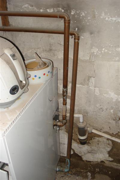
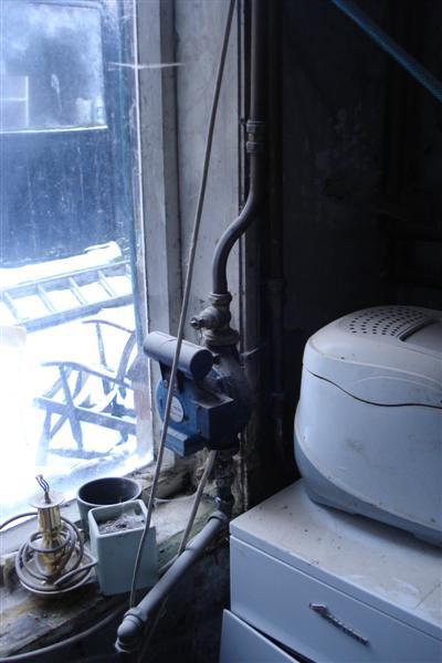
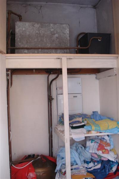
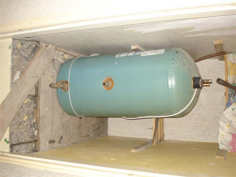
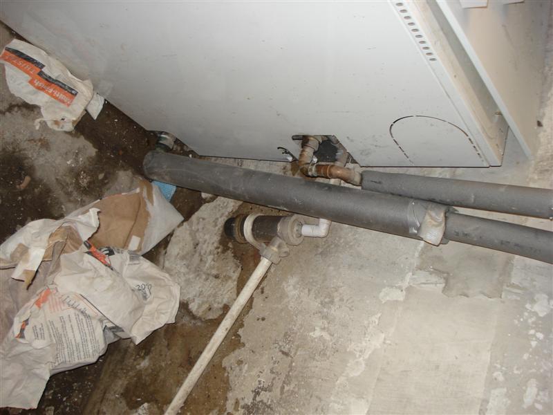
I have a greenstar utiltiy condensing boiler 18-25 kw boiler. My plumber explained that it was plumbed like a traditional gravity fed system rather than an S plan and was basically going to overheat.
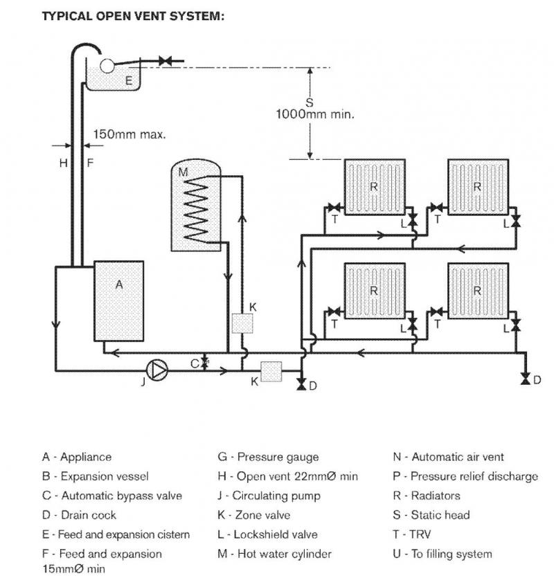
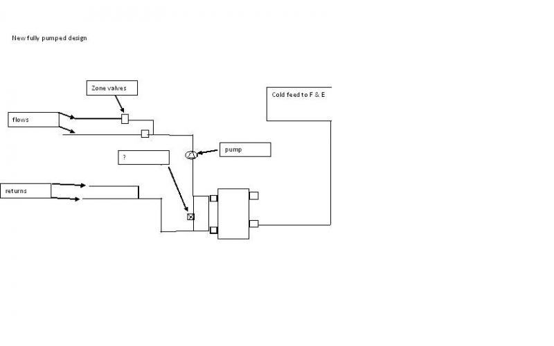
So basically the plan is fully pumped with thermostats added for both hot water and room temperature
I need 2 x 2 valves also, pump for over run.
I looked on Honeywell for diagrams but could not find a decent one with the pipes and valves positioning . i.e. I need to run a pipe from the F&E tank straigh to the boiler but which bit!?
How far from the pump do I fit the valves?
Any good links or pdf's people could post or email me?
Thanks guys
I recently had a plumber round to check over my boiler and service it and he noticed that my boiler was linked up incorrectly.
I have a greenstar utiltiy condensing boiler 18-25 kw boiler. My plumber explained that it was plumbed like a traditional gravity fed system rather than an S plan and was basically going to overheat.
So basically the plan is fully pumped with thermostats added for both hot water and room temperature
I need 2 x 2 valves also, pump for over run.
I looked on Honeywell for diagrams but could not find a decent one with the pipes and valves positioning . i.e. I need to run a pipe from the F&E tank straigh to the boiler but which bit!?
How far from the pump do I fit the valves?
Any good links or pdf's people could post or email me?
Thanks guys