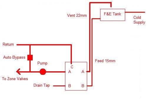
Drain Tap is difficult to get to as it's next to a wall, can I just add a drain cock on the F& E feed (also a B outlet). I noticed the F & E feed is 15mm rather than 22mm is this normal? I was thinking that's a big reduction on the boiler outlet!?
I have been looking at the logisitcs of the layout and and am very pleased to have a plan!
I do however see myslef having to run more pipes up to the loft than I would like (if it needs to be done it, needs to be done!).
Is there anywhere else I could tee the F&E vent pipe from rather than from A on the right hand side? It just means hassle of making room in the joists and a fair bit more copper!?
Is there anywhere else I could tee the F&E vent pipe from rather than from A on the right hand side? It just means hassle of making room in the joists and a fair bit more copper!?
Where is the pump located? If it is on the flow from A (left) on the boiler, both the feed pipe and the vent pipe can be installed this pipe. Then the RH A and B connections are not used. See my earlier post about correct order.
The problem which has to be solved is making sure that there is not an excessive pressure difference between the feed connection and the vent connection. This is why the distance apart must not be more than 150mm (The pressure drop across the boiler is about 60mm)
PS How exactly are the feed and vent pipes connected at the moment?
The pump is located exactly as you put it in your diagram.
As to how the heating is at the moment well there isn't any as I have removed the old tanks and am in the process of installing new ones.
The plumber said it was all wrong so I disconnected it all. A and B on the right hand side I think were connected to the HW tank so he said that there was a danger of it overheating.
He seemed to think I would need a 22mm pipe going to the right hand side (feed for the F&E I think) and block the other outlet off but this involves extra pipe?
I was thinking more of it's actual location. If the pump is right next to the boiler you have two choices:
1. Install the vent pipe as in my diagram.
2. Relocate the pump so it is in the airing cupboard with the HW tank.
The feed and vent pipes are then connected to the flow from the boiler just before the pump. They can connect anywhere on the pipe between the boiler and the pump as long as they are in the correct order and no more than 150mm apart.
Of course, if the pump is already in the airing cupboard, just below the tank, you can connect the feed and vent pipes there.
He seemed to think I would need a 22mm pipe going to the right hand side (feed for the F&E I think) and block the other outlet off but this involves extra pipe?
If you need to find a tradesperson to get your job done, please try our local search below,
or if you are doing it yourself you can find suppliers local to you.
Select the supplier or trade you require, enter your location to begin your search.
Please select a service and enter a location to continue...
Are you a trade or supplier? You can create your listing free at DIYnot Local