Scantronic 9800 controller, need connections to Elmdene SAB!

Joined
31 Dec 2011
Messages
19
Reaction score
0
Location
Northamptonshire
Country
United Kingdom
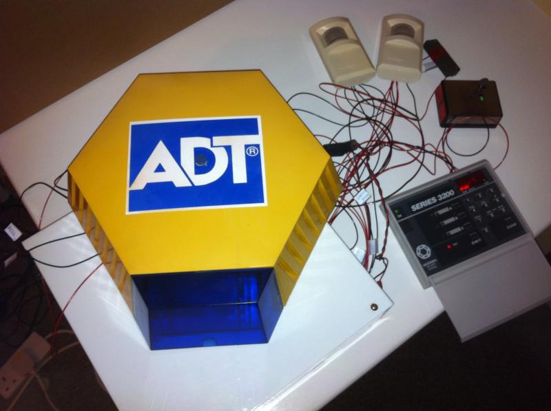
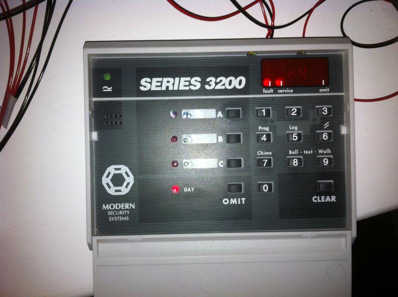
I inherited what I now believe to be an ADT alarms system with my home; a SCANTRONIC 9800 system. Due to various works around the home I disconnected the system some years ago. I did myself a wiring diagram and so have all the termiantions noted with the exception of the outdoor sounder and beacon (SAB). From my investigations, this is an ELMDENE module although I do not know the model number.
There were 4 cables from my 9800 panel wired to the ELMDENE device, these are screened on the PCB as TR(yellow) 0V (black) 12V (red) and BELL (blue).
The ELMDEENE SAB has the following designations, +H, -H, RTN, -R, ENG, BATT and ST-. There is also a small link, hardwired from the PCB, I believe the other end of this link wires into the ENG terminal to stop the sounder when commissioning the system?
Can anybody advise me on the interconnections between the two modules? :?:
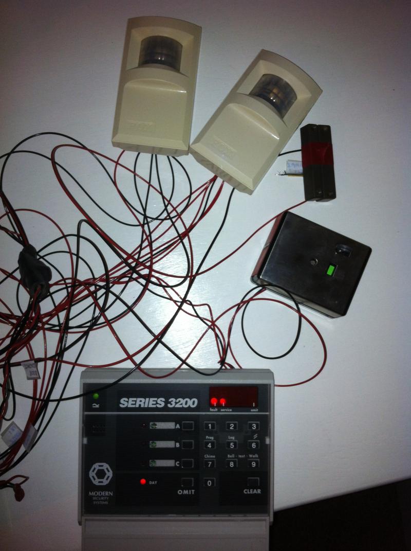
I currently have the whole system wired in my living room whilst I try to familaries myself with the system. I note that I currently have no battery connected, I will need to puchase a new one ASAP.
Help/Advice will be very much appreciated :!: :!:
 
Sponsored Links
+H is red/ -H black/ RTN is yellow/ -R is blue the wire link if its a black lead connected to pcb should go to batt if you dont have a spare core for ST- strobe you can link it to -R in bell box
 
+H is red/ -H black/ RTN is yellow/ -R is blue the wire link if its a black lead connected to pcb should go to batt if you dont have a spare core for ST- strobe you can link it to -R in bell box

Hi Sparkymarka, Out of interest, (A) what does the -R stand for and (B) what is the ENG terminal used for. Is there anyway to run the SAB unit silent whilst commissioning. As i Mention, is all setup in my living room and currently driving familymad as I bugger about with it.
(thanks for your quick response earlier)

+H = +ve Hold?
-H = -ve Hold?
RTN = Tamper Return?
-R = ?
ENG = Engineering Mode??
Batt = Bell Unit internal Battery??
ST- = Strobe?
 
The eng terminal / link keeps the sounder from ripping your ears off.
For test purposes.
Once your satisfied all is well cut it and the sounder goes to a 15 min timer.

-R is the negative trigger to activate the sounder.

IMHO the best sounder on the market.
 
Sponsored Links
The eng terminal / link keeps the sounder from ripping your ears off.
For test purposes.
Once your satisfied all is well cut it and the sounder goes to a 15 min timer.

-R is the negative trigger to activate the sounder.

IMHO the best sounder on the market.

Sorry mate, some more questions...... :oops:

I have now wired my test system as you recommended and there appears to be a little more logic to my test scenario; the bell and strobe certainly operate when one of my circuits is set to alarm. (1) To clarify, the other end of the black link from the SAB PCB is now wired into the BATT terminal. What do I link to the ENG terminal to save my ear drums :!: :?:
(2) I have 4 circuits wired into my SCANTRONIC, x2 PIR (N/C and TAMPER), x1 Panic Switch, x1 magnetic door contact. All circuits are stable in their N/C condition, the covers are on my SAB, keypad and main controller, so all tamper circuits are made and the system is healthy.
The Series 3200 keypad is on (green Led), its is in Day Mode? (red Led), the display indicates FAULT and SERVICE and the display flashes r4 (remote Keypad back tamper?)
Both the keypad and SAB are silent (no audible alarm)
If I check the recent alarm log its cycles bF (battery Fault), this is fair enough as no battery is currently connected and rr, Installer reset required. This rr concerns me, does this mean I will not be able to get my system up and running without spending £££ with ADT systems?
To recap, my system has been decommissioned for nearly 2 years with no power and no battery connected.....will I be able to recover this system without involving the professionals. The system appears to have stored my 4 digit user number and for example, when I disconnect the Panic Alarm, PA is displayed, so it must still have its original program stored.
I have read on the web that having no battery connected can give you spurious rogue error codes on your keypad?
 
It needed a fully charged battery to work.
You will not get it functioning without.

That is all.

ADT will not fix they will want to replace and put you under contract probably 24 months.

Buy a new battery and we can fix it as "Bob" used to say.
 
PS is it the yellow bow rather than the rectangular stainless steel sounder?
 
PS is it the yellow bow rather than the rectangular stainless steel sounder?

I have created a SCANTRONIC 9800 album which contains pictures of my test system, this may help you identify my equipment(s).


It sounds like I cannot go much further with my tests until I get my hands on a new battery. I will pick one up on Tuesday.
Any further comment regard the ENG link :?: What do I have to link to the ENG terminal for "silent running" :)
Thanks for all your support to date, very much appreciated. Wish you a happy new year, correspond again soon....... [net][/net]
 
Lol. That looks tidy, got to check. With. That link as am in the pub and the bad singer. Has ****ed off!!
 
Lol. That looks tidy, got to check. With. That link as am in the pub and the bad singer. Has **** off!!

:D Yeah, only had two drums of multistranded black and red, looks a mess but all labelled up so I know what the score is. All the existing cables still in situ around the home so should I be able to make the test system operate again it will not be too much trouble to reinstall....anyway, will let you recover from any hangover you may have acquired from last night ;) :!:
Would really appreciate details on the ENG link, getting really fed up with the siren !!! :(
I still have the r4 alarm on the keypad, I think this may relate to the tamper on the keypad?, every time I appear to touch or move the keypad the Keypad alarms locally (not the SAB), although I cannot seem to clear the r4. (introducing battery Tuesday so we wait to see if this clears)
My keypad always indicates DAY mode (red led illuminated). Is this an INACTIVE mode, i.e. family/pets around the home so system does not report alarms?, if so how do i ARM the system?
I apologise for what may seem silly questions, but I have no operating instructions for keypad. I currently have very little idea how to operate or configure the system. :(
 
I don't think you are reading the fault code correctly, there is not an 'r4' fault code from this panel, which by the way is a Scantronic 9800 re-badged as the Modern Alarms Series 3200.

The list below should help if you don't have the User Manual that shows these

c1 to 8 Detector circuit open.
t1 to 8 Circuit tamper open.
o1 to 8 Detector circuit omitted (isolated).
E1 to 8 Entry via a detector circuit.
S1 to 8 Detector circuit on Soak test.
EA Alarm on entry
EF Exit fault
bF Control panel battery fault
PF Mains supply failure.
Sr System reset (Total power failure).
AP Aux. (Detector) power failure.
Lb Control panel low battery.
rt Illegal use of keypad (excess number of keypresses).
rP Remote keypad missing.
rr Total power failure (engineer reset required).
u1 to u9 User access number (U5 = Duress, U9 = Keyswitch)
AE Access Engineer
AA Arm area A (Full set).
Ab Arm area B (Part set).
Ac Arm area C (Part set)
Lt Control panel tamper.
tr External bell tamper.
cF Communications failure (External signalling).
LF Telephone line fault.
cc Communications completed successfully.

Europlex, thanks for your input & codes :)
Unless I have a fault with my display, but lower case r and 4 is being displayed (zoom in on one of my 3 pictures, you can see it faintly), from what I have now read from a 9800 User Guide (downloaded PDF) r1 - r4 (Remote Keypad Back Tamper), I believe (again,reading the literature) that this system can have a maximum of 4 keypads attached, so the codes r1 - r4 make some sort of sense :?: :!:
 
What is the keypad addressed as?

Alarm,

I am 99% certain the keypad had all the switches in the off position, down (will check again tomorrow morning). I think this indicates "No Address"? There was only ever one keypad on my system when I inherited it.
 
Bit late and a while since I played with a 9800 but the keypad has to be addressed.
No doubt some bright "spark" will dispute this.
 

DIYnot Local

Staff member

If you need to find a tradesperson to get your job done, please try our local search below, or if you are doing it yourself you can find suppliers local to you.

Select the supplier or trade you require, enter your location to begin your search.


Are you a trade or supplier? You can create your listing free at DIYnot Local

 
Sponsored Links
Back
Top