What is the point of your idiotic meaningless nonsense post?What is the point of this idiotic piece of meaningless nonsense

You are using an out of date browser. It may not display this or other websites correctly.
You should upgrade or use an alternative browser.
You should upgrade or use an alternative browser.
Spurring sockets
- Thread starter greenstarthree01
- Start date
So to what extent should we be like the plumbers and tell people things which are untrue simply because a proper explanation is too much effort?No. not allowed.
The FCU must protect all of the spur.
That's a bit cryptic but I think I know what you mean.
in view of the way the thread started and continued, I thought it was more about the placement of the FCU rather than could you get away without one?
However, as you have probably raised the OP's curiosity, you could suggest such things, hence pointing out that there is never a need for an FCU and be accused of more dangerous nonsense by some.
- Joined
- 27 Jan 2008
- Messages
- 28,913
- Reaction score
- 3,538
- Location
- Llanfair Caereinion, Nr Welshpool
- Country

I think the old idea of calling the cable out of the FCU a radial avoided confusion. But in real terms the whole idea is to avoid over load of the cable, and if supplied from 2 x 2.5mm² then in the main it will not be overloaded when protected by a 32A MCB, but if supplied from a single 2.5mm² then some thing needs to reduce the protection device to 22 amp, OK 2 x 13 = 26 but it is assumed that you will never draw 26 amp for long enough to damage the cable. If we could get 20A fused units then there would be nothing to stop us using a 20 amp FCU but we can't so we have to work with what is available, be it a grid socket with one socket and fuse in same unit or a wider back box and two independent units it is down to what we want to do.
One odd bit of the rules is can't have 2 x single sockets, but can have a double socket on an unfused spur, I guess because some one may see two cables into a single socket and assume it is a ring, as to having two single grid sockets in a single grid plate not sure if this is counted as two single sockets or one double, I would think the latter.
However we consider a 13A socket as fused as nearly all 13A plugs have a fuse in them, there are some medical exceptions, so question is could what you have done either allow overload or make some one in the future think it was part an a ring final if they simply looked but did not test socket, if so then not allowed.
I wouldn't point that out, as it is untrue.... hence pointing out that there is never a need for an FCU ...
I don't know what you meant, then.
I obviously might be wrong, but I suspect that he may well have been being confusingly (for the OP, and most other readers) pedantic and attempting to refer to the fact that nothing in the regs (only the guidance in Appendix 15) explicitly says that multiple sockets (or whatever) cannot be supplied by an unfused spur from a ring final circuit. That being the case, it follows that, strictly speaking, a designer can connect whatever he/she likes (including multiple sockets) to an unfused spur if they do so in a manner that would be compliant with all other regulations.I don't know what you meant, then.
As often discussed, one way of achieving that would appear to be to wire the unfused spur in 4mm² cable (a possibility which is not considered by the guidance in App 15) - but there may well be other possibilities. Multiple FCUs hard-wired to very small loads (e.g. lighting transformers) might arguably be another.
Kind Regards, John
Where you see "confusingly pedantic" I see an incorrect comment regarding this:
Are you suggesting that a proper explanation of the issues should not be attempted because that would be confusing pedantry?
Are you suggesting that a proper explanation of the issues should not be attempted because that would be confusing pedantry?
- Joined
- 27 Jan 2008
- Messages
- 28,913
- Reaction score
- 3,538
- Location
- Llanfair Caereinion, Nr Welshpool
- Country
I see your point, as long as the design will in the main prevent an over load, then no real problem, the same goes for lollipop and figure of 8.
However the question is complicated by the fact the installation is in the control of an ordinary person. I a factory when an electrician is in control it is far to say he should test before doing any work, so he can used any distribution unit he sees as fit for the job, it does not need to be type tested, it does not need to be a consumer unit, in a domestic home however we are restricted to using a type tested distribution unit call a consumer unit.
To be frank I am uncertain as to what is allowed when an ordinary person is in control? It is easy to remove a socket and put a meter between the two line, neutral, and earth wires and if connected assume you are breaking into a ring final and not a spur, and the ring is complete, however if before that point a figure of 8 exists, then the circuit the ring final is connected to could have a fault and be in essence a 2.5 mm² spur, one would need to remove the connections in the consumer unit and temporary connect as shown in Book 3 and go to each socket and measure the resistance line to neutral to identify which sockets are part of ring and which are spurs. Don't think I have done this since passing my C&G 2391 know I should but I was mainly commercial where there were not so many ring finals.
So the question is when what we are doing is safe, but could lead to some one in the future when not testing correctly or not having the paperwork for the circuit at hand making an error so introducing a danger, should we refrain from doing it?
So we all know no difference to cable loading with two single sockets or one double, however latter permitted on un-fused spur and the former is not. How far we should go protecting against some one in the future making an error is a big question. Splitting two ring finals side to side not up stairs and down stairs will likely reduce the circuit impedance so technically good, but some one could turn off the wrong circuit as a result, of course proper testing for dead would stop this, so if they get it wrong not really your fault.
But in the main we follow conversion as this in the main is safer even if the rules don't stop you using other methods.
- Joined
- 27 Jan 2008
- Messages
- 28,913
- Reaction score
- 3,538
- Location
- Llanfair Caereinion, Nr Welshpool
- Country
Where the problem lies is in the future some one may not test and wrongly assume the unfused spur socket is in fact part of a ring circuit.
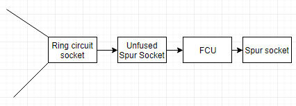
So a scenario which actually came up in my mothers house, asked for all sockets on rewire to be on the ring final so I could expand, find however the socket next to mothers bed is a spur could not find a fuse so seems likely unfused, I want to add two double sockets, so original double removed and replaced with a grid plate, with a single socket, a switch and a fuse holder, it can either be wired with or without the socket next to fuse holder going through the 13A fuse, and any one in the future will be able to see which way it is wired, I took all through the fuse, however it could have been wired as the picture shows with no worry about some one in the future making a mistake, as when the grid plate is removed one can see how wired. So find a good reason why the socket could not be wired before the fuse holder in this case, remember load can never be greater that a double socket can draw, and the grid plate will never allow you to replace the single socket for a double without removing the fuse holder.
If that is a response to the preceding post, whilst I agree that it is unlikely to result in a 'real problem', it represents something that the followers of the guidance in Appendix 15 BS7671 would say 'should not be done' - and (given the 32A OPD), even if one forgets App 15, would only be permissible in terms of of actual regulations if the CCC of the cable to the first socket were at least 26A (i.e. for 2.5mm², only if Method C).I see your point, as long as the design will in the main prevent an over load, then no real problem ...
Whilst some people would be able and willing to argue that something was acceptable despite contravening the guidance in App 15, it would be silly to suggest that many DIYers would want to be put in that position (regardless of what we think about the guidance). I'm sure that most of them would want to be able to say that they had worked in 'compliance' not only with the regulations but also with the 'official guidance'.
There's no 'not permitted' about it - you are again referring to the guidance in App 15 - so, as above, provided the (first bit) cable CCC is at least 26A, there is no regulatory problem with two single sockets.So we all know no difference to cable loading with two single sockets or one double, however latter permitted on un-fused spur and the former is not.
Don't forget that, if we were talking about a 2.5mm² radial with a 20A (or 25A) OPD, it would be allowed to supply an 'unlimited' number of (single or double) sockets. The only issue with a 2.5mm² spur from a 32A ring final (or, indeed, 32A radial) is the 32A OPD. Indeed, even if the 2.5mm² radial had a 32A OPD, one could probably argue that it was acceptable for it to supply two single sockets.
Kind Regards, John
One surely can't use that as an excuse for not doing something.Where the problem lies is in the future some one may not test and wrongly assume the unfused spur socket is in fact part of a ring circuit.
"In the future" someone could make any number of incorrect assumptions if they did not undertake adequate observation and testing to determine the true situation, and we cannot design on the basis of future possible incompetence/idiocy, can we?
Kind Regards, John
Are we treating all these sockets as single ones? The diagram shape does not indicate that to me.
Is that what I am supposed to have got wrong?
Is that what I am supposed to have got wrong?
I'm certainly not assuming that - but the arguments for it 'not being acceptable' are obviously stronger if/when one or both of the sockets is a double.Are we treating all these sockets as single ones? The diagram shape does not indicate that to me. Is that what I am supposed to have got wrong?
Kind Regards, john
- Joined
- 27 Jan 2008
- Messages
- 28,913
- Reaction score
- 3,538
- Location
- Llanfair Caereinion, Nr Welshpool
- Country
Early it was stated if two cable are connected to the socket then it is either part of a ring or part of a fused spur or part of a radial. If only one cable then it is an unfused spur or last socket from a radial or fused spur and more investigation needs doing.
Of course some one could have broken or bent the rules, as you rightly state it is up to the designer to ensure any over load will be both rare and for a short time, I do remember doing the calculations, with a ring final where the cable is rated 22A and the supply is 32A how far from the consumer unit the first few sockets needs to be to ensure one leg is not overloaded.
Without getting the books out I suspect with 100 meters of cable 50*32/44 = around 35 meters into the ring before we could be 100% sure that three sockets would not draw over the 22A rating of the cable. However it is rare to load sockets to the maximum and with the 2000W limitation for non portable about the only item which can use 3 kW for an extended time is a room heater, in real terms only time I have seen sockets loaded to maximum is when the builder plugs in loads of heaters to dry out plaster.
Where the problem arises is with fixed appliances over 2 kW fitted close to the consumer unit, or tapping on to the ring with figure of 8 too close to consumer unit, or point where a lollipop circuit splits. As often said an electrical installation should be designed, not thrown together, following the guidance in the appendix one is unlikely to have a problem, but once one leaves the security of following the appendix or on site guide one has to be far more careful.
Where the problem lies is additions, on a rewire it is easy to arrange it so there is unlikely to be an overload. However you find a socket with two cables going to it, and you want to add more sockets to that point, OK you can plug in the loop impedance tester into all sockets on the circuit and work out which sockets are close to the consumer unit and which are near the center, however hardly an option for the DIY guy.
So let us assume a scenario a double socket in the kitchen in England and the home owner want to add to that socket, it has two cables going to it, the consumer unit is the other end of the house, so if a standard ring final no problem, if however a lollipop if too close to where it splits from the 6mm to two 2.5mm cables it could cause an overload. So question is how would you instruct the DIY man to test so he knows if he can or can't add an extra socket? It is OK for us, we can look at the cable in the consumer unit and say that's 6mm must be a lollipop circuit, but for DIY guy not so easy, so how would you tell him to test to be 100% sure there will be no overload?
DIYnot Local
Staff member
If you need to find a tradesperson to get your job done, please try our local search below, or if you are doing it yourself you can find suppliers local to you.
Select the supplier or trade you require, enter your location to begin your search.
Please select a service and enter a location to continue...
Are you a trade or supplier? You can create your listing free at DIYnot Local
Similar threads
- Replies
- 85
- Views
- 22K