Oh dear.
After continuity you'll need to test for voltage.
I need to simplify my task and not have to spend my time telling people how to do the simplest thing!!!!.
The meter comes with an instruction book. Look under continuity......
RTFM!!! /rant over/
OK. I'll try to help, a little.
I asssume the thing has batteries in it and a display is shown when its switched (see "switching on" in the manual)
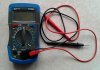
With the leads in the sockets per your picture, move the control knob round to the half past 5 position (the symbol that looks like a speaker between the 200 and teh hfe position)
touch the two test leads together, you should get a beep. That shows continuity. That is how you test continuity.
Simples
PS
Before you experiment on your house wiring you need to turn off the voltage and use the multimeter on the voltage range to confirm the power is disconnected.
But then you'll need to test for voltage.......