Toroidal transformer for 12V track lighting?

  • Thread starter attractivebrunette
  • Start date
A

attractivebrunette

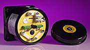
I have a toroidal transformer to be use for 12V track lighting.

The transformer has the primary blue and brown wires.

The four 12V wires are as follows:

SEC: 0-12V RED YELLOW
0-12V BLACK GREY

Which of these wires do I join before connecting to each of the two 12V tracks?
 
Sponsored Links
Just to add I'm only interested in helpful replies from genuine electricians. Thanks.
 
Sponsored Links
Will an electrical engineer do?

I'd put the windings, properly phased, in parallel for better voltage regulation.

Signed
Physically Repulsive Engineer
 
Porque won't see this, so could someone else suggest that he spends a bit of time looking over attractivebrunette's body of work here? And not just the electrical stuff - her saga of the flue liner or chimney liner is a classic.
 
The data sheet should give the information you require this one for example states
Secondary windings can be connected in series or parallel or used independently.
but not all will be wired that way.

The transformer like this
42407106.jpg
is designed to be used within an enclosure and I would not select that type for powering lights. This type
TLT200SLASH4.JPG
are designed for lighting and have a lid which hides all the connections requiring a tool to access live parts.

Since there are two 12 volt tracks why do you want to join anything together? Clearly better to run independently.

You can clearly see on the top picture that transformer has all the connection details on the transformer its self I would think most are like that.
 
I'd put the windings, properly phased, in parallel for better voltage regulation.
That only works if the transformer is designed to have its windings connected in parallel.

That requires the same number of turns to ensure the same voltage.

The windings need to have the same impedance if they are to share the load equally. Poor load sharing at the maximum rating for the transformer will result in one winding becoming hotter than the other and this can cause thermal and/or mechanical stress in the transformer.

Bifiliar secondaries are the best option for parallel connection.

For non parallel operation bifiliar suffers from having a low breakdown voltage between secondaries.
I believe I've thought of that.
If V1, Z1 and V2, Z2 are the voltages and winding impedances then paralleling them with no load would give an I of (V1-V2)/(Z1+Z2). If this I is less the winding current rating I'd say it's OK for one winding to sink or source this much current. And with a load both windings would source current.
 
I believe I've thought of that.
If V1, Z1 and V2, Z2 are the voltages and winding impedances then paralleling them with no load would give an I of (V1-V2)/(Z1+Z2).
Do you mean impedance or resistance. With counter connected ( out of phase ) secondaries the affect on the magnetic flux is likely to lower the impedance. A fact confirmed by more than a few burnt out transformers with incorrectly sleeved secondaries.
I'd put the windings, properly phased, in parallel for better voltage regulation.
You thought of it but did not mention it. Your advice to connect them in parallel without mentioning the need to have identical windings could have created a problem or hazard to the OP.
 
You thought of it but did not mention it.
I think it's worse than that. He now seems to be suggesting that it's OK to connect two windings with different voltages and/or impedance in parallel so long as the the rating of the transformer is not thereby exceded under no-load conditions.

Kind Regards, John
 
Red to one track, yellow to the other track

But check that you will have enough current out of one transformer winding to run all the lights?

Total bulb wattage divided by 12volts = minimum required current
 
You thought of it but did not mention it.
I think it's worse than that. He now seems to be suggesting that it's OK to connect two windings with different voltages and/or impedance in parallel so long as the the rating of the transformer is not thereby exceded under no-load conditions.

Kind Regards, John
It's much worse than that.
I think you can connect dissimilar transformers in series or parallel for current sharing or voltage increasing with some cases requiring resistors to alter the current sharing.
The two cases to be checked are full load and no load (if the application ever has the transformers unloaded).
It's easy enough to find the winding R but getting the winding Z and its angle is more difficult.

Once you have the Thevenin equivalent circuit of the secondary you can mix and match but for final tweaking you may need to go to the test bench.

I will say, however, that if you have one 30 kV neon sign transformer and you connect two 7.5 kV transformers in series with it to get an even longer arc, the 7.5 units will soon short and you're back to 30 kV. :(
 

DIYnot Local

Staff member

If you need to find a tradesperson to get your job done, please try our local search below, or if you are doing it yourself you can find suppliers local to you.

Select the supplier or trade you require, enter your location to begin your search.


Are you a trade or supplier? You can create your listing free at DIYnot Local

 
Sponsored Links
Back
Top