Any idea on this though?
Would it be wired like the pump output? With 3 going to 230V and 4 going to the UFH zone valve? Just an amateur suggestion. Needs checking.

Any idea on this though?

So I haveIn your 'pencilled' diagram, it seems you already have a salus programmable room stat for the CH and I presume programmable room stats for each UFH zone? or are they just stats and not programmable?
Is hive programmable? I.e timer option built inThey lose contact for fun, very unreliable, if you already have them for your UFH just leave them until they fail, I would use single channel Hives for the other zones, obviously you will need 2 apps to control everything, for the hive zones you will need a thermostat and receiver for each zone but they can share 1 hub
Belter! @Madrab could change his username.Pasting Madlabs post from other thread:
Haha, typo. I got it right at the bottomBelter! @Madrab could change his username.
Or even madladBelter! @Madrab could change his username.

I need to check if that's a volt free switch, if it is then the boiler switch on the UFH controller will need a perm live in, so when it switches it sends that live out (Switched Live) to the UFH 2 port Live (Brown)Do I need to use only one of them as the live out from Ufh control centre to the valve
Seems Volto free.I need to check if that's a volt free switch, if it is then the boiler switch on the UFH controller will need a perm live in, so when it switches it sends that live out (Switched Live) to the UFH 2 port Live (Brown)
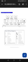
Yep that's the one. So should I send a perm live into one of the holes too? And use one wire out to the valve/pump?It's a Salus KL08NSB controller? If so then both the boiler and the pump switches are volt free (com/no)
Yes, follow the manuals wiring advise, the live in would run in through the com and the live out (SL) would be from the NO to the live on the 2 port to energise the valve. The pumps mentions 240V but the boiler doesn't so I need to see if there is a rating somewhere for the boiler switch.Yep that's the one. So should I send a perm live into one of the holes too? And use one wire out to the valve/pump?
If you need to find a tradesperson to get your job done, please try our local search below, or if you are doing it yourself you can find suppliers local to you.
Select the supplier or trade you require, enter your location to begin your search.
Are you a trade or supplier? You can create your listing free at DIYnot Local