S plan and UFH

Joined
20 Feb 2021
Messages
43
Reaction score
0
Country
United Kingdom
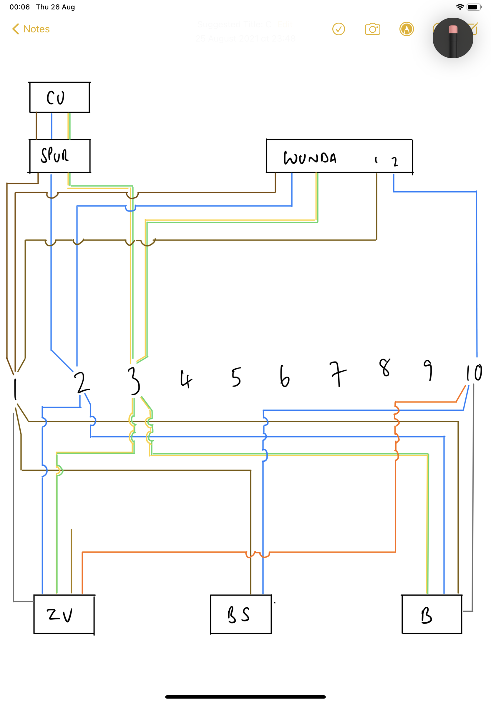
I am refurbishing my home and will have UFH on the ground floor and first floor, replacing all the radiators in the home.
My boiler is an oil fed external combi boiler and I'm going to be using an UFH system from Wunda.
Currently with the radiators there was no S plan wiring, I assume as technically it was all one zone, but I'm led to believe this time round there should be.

Is there any recommended sources where I can learn and understand how this wiring will go together for my set up?
I'm all sorted with the plumbing side, and was happy with the wiring from components to the UFH wiring centre however now with this S plan its thrown a spanner in the works.
 
Sponsored Links
Not sure of the technicalities re: having to have zones.
Probably better off in the Plumbing forum. I'll get you moved.

You say you are sorted with the plumbing so how have you designed it?
 
Thanks to whoever moved my thread across, was just about to ask if this could be done.

Plumbing wise, I've got a 22mm flow and return going to a buffer vessel from the external oil fed combi boiler. Then a 22mm flow and return going up to the upstairs UFH manifold. On the flow side before it gets to the manifold there is a 2 port zone valve after which it goes through the blending valve and pump.
From there its then distributed to whichever of the 5 zones call for heat before the return comes back down to the buffer vessel.

I've only recently looked to include a buffer vessel as more research into UFH especially with oil fed boilers is saying by adding the buffer vessel to be used when the manifold calls for heat, reduces short cycling of the boiler. And as oil fed boilers are just on/off this should hopefully reduce wear and tear.
 
S plan is just two or more valves in the flow to two or more zones.
What those zones are doesn't matter - traditionally it was a hot water cylinder and radiators, but can be anything, including HW cylinder(s), multiple radiator zones, multiple UFH zones or any combination of those.

Valves are closed by default, applying power opens the valve and allows water to flow.
Power applied to the valve from the UFH controller, or room thermostat for radiators, or cylinder thermostat for hot water cylinder.
Valve has a switch inside which is used to activate the boiler & pump on conventional systems, or just the pump on those with a buffer vessel.
Multiple valves = all of the switches commoned together so that one or more open will activate the pump / pump & boiler.
 
Sponsored Links
With oil there is no problem using motorised valves as the boiler does not modulate, so having the valve on/off rather than using analogue control does not matter, but there is only one micro switch in a motorised valve, and you need to control two or more pumps independently to the boiler, so some where likely you need a relay so the single micro switch in the valve can control two things, the normal method is a special relay panel all pre-wired to do the control.

In my home the main house and flat have their own pumps and motorised valves but common boiler, so I have same problem, I have to use relays so I can switch pump and boiler independently.
 
Thank you for the responses. It's certainly helping me get my head around S plan wiring.
My rough drawing of the UFH system for the first floor is here
B31B012B-2098-41B7-A5A7-8DF9143B0705.png

and the wiring diagram for the Wunda wiring centre I'll be using is
30BBE680-F7DE-4F5D-B981-3C4A4EC508C1.jpeg

So where I'm still struggling to make sense is this wiring centre will be upstairs above the manifold.
Do I put just the upstairs zone valve into the S plan wiring centre before going into the Wunda wiring centre?
Next year when the ground floor gets refurbished with UFH I'll add a second zone valve but that will be just before the manifold flow.
Or do all the connections go into the S plan wiring centre before going into the Wunda???
This is where I'm getting confused as to me it just makes more sense to go from the component into the Wunda wiring centre.
 
Last edited:
Hi all,

So I've sorted my plumbing out. A little bit different from before in that I've now removed the zone valve before the manifold and have introduced one to be between the buffer and boiler only. I'm thinking of having 2 sets of heating flow and return tapped into the buffer so I have a seperate feed for the upstairs and downstairs (when this is finally installed) UFH manifolds. Saves me having to install a tee later on and means I can put this part to bed soon as its down.
I've drawn up this schematic for my S Plan wiring centre and I hope most of it is correct. I'm lost as to where the brown cable from the zone valve (which is to go between the buffer and the boiler) goes so hoping someones can advise. I'm thinking 4, but can't work out what else should be there. Looking over this again I believe this should be the 'call for heat' from the buffer stat which I've indicated in brown going to 1. I say this as the COM from the stat is going to 10, switched live. So some help here is greatly appreciated.

I've looked through the MI for the boiler and all I can make out is a T&E for power, but unsure what else is going from it to the wiring centre. I've put in a SL in my diagram as I can make that out, but unsure if there should be another. I'm starting the rip out for the bathroom and floorboards on the first floor tomorrow so I'll be sure to see what other cables there are going to it at present.

Also I've got hold of the buffer stat instructions from Newark Cylinders and according to that its a 2 core cable (COM and 1, which I believe to be 'call for heat').

So here it is, if anyone can help then that would be much appreciated.


Why a motorised valve between boiler and buffer? If the boiler is only heating the buffer (dhw presumably all handled by the combi bit) and there's no other heat source into the buffer then you don't need it & it'll be a potential pain sorting out a delay off relay (assuming the boiler pump runs to cool the hex after call for heat is satisfied).
Your dual feed & return sketch is fine but means you'll need 3 pumps- one between boiler and buffer and one in each of the 2 feeds (or returns).
Your wiring diagram is a bit of a fail. You've got the zone valve permanently energised and the boiler stat (BS?) doing nowt. Normal setup is;
Live into controller (time clock, programmer). Switched live out of controller to thermostat Common. Normally Open contact of stat goes to live of motorised valve. Switch on MV controls signal to boiler and pump (either connects live or can make an ELV circuit if your boiler uses that signalling system- of course you'd need a relay for that trick cos the valve microswitch is SPST.
 
Last edited:
Why a motorised valve between boiler and buffer? If the boiler is only heating the buffer (dhw presumably all handled by the combi bit) and there's no other heat source into the buffer then you don't need it & it'll be a potential pain sorting out a delay off relay (assuming the boiler pump runs to cool the hex after call for heat is satisfied).
Your dual feed & return sketch is fine but means you'll need 3 pumps- one between boiler and buffer and one in each of the 2 feeds (or returns).
Your wiring diagram is a bit of a fail. You've got the zone valve permanently energised and the boiler stat (BS?) doing nowt. Normal setup is;
Live into controller (time clock, programmer). Switched live out of controller to thermostat Common. Normally Open contact of stat goes to live of motorised valve. Switch on MV controls signal to boiler and pump (either connects live or can make an ELV circuit if your boiler uses that signalling system- of course you'd need a relay for that trick cos the valve microswitch is SPST.

Hi, tbh the zone valve was advised to me hence it being in place.
With regards to the pumps, I assume the combi already has one (there isn't an external one fitted at present and the system runs fine albeit with radiators), and the manifold now, and in the future when the ground floor gets UFH, has a Wilo pump already fitted.
Boiler is an external oil fed combi from Worcester Bosch and from reading through that manual it notes a pump.
On to my wiring diagram am I right now in that the brown from the boiler stat goes to 10, and the blue will go to 4?
And the blue (COM) of the boiler stat goes to 4 along with the brown from the zone valve?
 
Still curious about the zone valve between boiler and buffer but probably won't do any harm (do check the MI for the boiler, see what it says about pump run-on).
Do you currently have a buffer- if not then that explains why system currently works just on the combi pump. You will need another pump on the circuit out of the buffer as well as the pump running the UFH.
You're confusing me with your wiring centre- all that is doing is giving you a tidy way to terminate the cables from various bits of the system. As far as I can tell, the Wunda thing generates a Call for Heat by making a circuit at block 5 (between pins 1 and 2). I'm assuming the rest of it is doing UFH specific things. That heat will be delivered by the buffer so all that pair does is power the OUTPUT pump from the buffer (currently not fitted), it doesn't connect to the S plan at all.
Back to your S plan wiring it should work as I described earlier.
You'll help yourself by redrawing that schematic and leave out device neutrals and earths- that'll make your switching much easier to see

Thanks for you reply. I've attached an updated version of the wiring which I believe now to be correct and have omitted the zone valve. Still has the earths and neutrals but I have also shaded brown over any cables that will be live to indicate sleeving to be used. It now makes more sense to me for the switching sequence with how this will work. Seeing it all drawn out has definitely helped me understand it and what is happening.
I've spoken to Wunda and Wilo with regards to the pump function and both confirmed the circulating pump on the manifold will be able to draw from the buffer and supply out to the zone/s calling for heat.
SPlanWiring.PNG
 

DIYnot Local

Staff member

If you need to find a tradesperson to get your job done, please try our local search below, or if you are doing it yourself you can find suppliers local to you.

Select the supplier or trade you require, enter your location to begin your search.


Are you a trade or supplier? You can create your listing free at DIYnot Local

 
Sponsored Links
Back
Top