

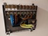
I have a Danfloss tp9000 programmer and TS2 room sensor which is controlling the Ideal Heat 15 system boiler.
I'm trying to replace it with a smart thermostat by Nest, replicating this set up https://d3vlabs.com/2016/12/09/install-nest-tp9000-ts2-danfoss-3rd-gen-uk/
There are 3 lives, 3 neutrals one grey to call Hot Water T3 and brown to call CH on T4, this is all straight forward more or less. Than there is a brown and black two core cable on terminals T5 and T6 for the remote sensor TS2, which I wanted to re-use to power thermostat via 12V DC supply from heatlink, as I thought this is just a straight connection to TS2.
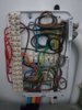
My problem is when I turn the power off on the boiler I still measure 5V AC on between two cores on room sensor wiring. Even when I disconnect the cable on both ends (sensor and programmer) the ac voltage is there. It goes away obviously when master is off on the board.
I struggle to understand this. If the cable goes somewhere else, why and where? If this is induction then 5V is quite a lot, but sensor is working fine somehow despite this.
I've got a wiring central next to hot water cylinder in cupboard. I tried to find these 5V but there is nothing.
There is also a second zone for bedroom CH, which should not matter I thought, as it runs from another tp5000 and there is no external sensors.
Please help, as I don't really want to try connecting thermostat to try it out.
I'm trying to replace it with a smart thermostat by Nest, replicating this set up https://d3vlabs.com/2016/12/09/install-nest-tp9000-ts2-danfoss-3rd-gen-uk/
There are 3 lives, 3 neutrals one grey to call Hot Water T3 and brown to call CH on T4, this is all straight forward more or less. Than there is a brown and black two core cable on terminals T5 and T6 for the remote sensor TS2, which I wanted to re-use to power thermostat via 12V DC supply from heatlink, as I thought this is just a straight connection to TS2.
My problem is when I turn the power off on the boiler I still measure 5V AC on between two cores on room sensor wiring. Even when I disconnect the cable on both ends (sensor and programmer) the ac voltage is there. It goes away obviously when master is off on the board.
I struggle to understand this. If the cable goes somewhere else, why and where? If this is induction then 5V is quite a lot, but sensor is working fine somehow despite this.
I've got a wiring central next to hot water cylinder in cupboard. I tried to find these 5V but there is nothing.
There is also a second zone for bedroom CH, which should not matter I thought, as it runs from another tp5000 and there is no external sensors.
Please help, as I don't really want to try connecting thermostat to try it out.

") .
.