Wiring a new motor for kingspan klargester

Joined
30 Apr 2025
Messages
8
Reaction score
0
Country
United Kingdom
Hello everyone.

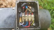
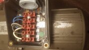
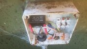
I have bought a replacement motor for my BA biodisc klargester. Unfortunately for me the new motor is an updated version made by panasonic and wiring is a bit different. This new motor has 5 connections where the old motor had 4. Im trying to figure out where the wires go on this new motor, I will post some photos of old and new motors. There is a capacitor unit box which the wires go through on inside of klargester. Any help is appreciated thank you.
 

Attachments

  • old motor.jpg
    old motor.jpg
    215.3 KB · Views: 88
  • new motor.jpg
    new motor.jpg
    181.2 KB · Views: 70
This is the old motor with wiring diagram. Thanks.
 

Attachments

  • 20250430_214756.jpg
    20250430_214756.jpg
    212.9 KB · Views: 58
You need to ask the supplier or manufacturer for a wiring diagram suitable for UK use, unless someone on here has previously installed one.
 
@chips51 Are you sure that 'new' motor is new? Looking at the corrosion/rust on the screws of that terminal block, I think it has been in use before.
 
Sorry the motor has been refurbished, Its a second hand unit.
 
Thank you for your replies.

I have found this page on the internet which seems to be a data sheet of this motor. It says I need a 3uF capacitor. As I have a 2uF installed this will need to be changed.

I just want to see how far I can push this along before I consult the professionals.

The page also says the 2 blue wires are for a stop start latching circuit. I have no idea what that is yet so more research is needed. I'm sure the old viper motor didn't have that.

Also I think the screw near the connector is the earth connection.
 

Attachments

Might be worth asking in the Electrical section, I know how the Biodisc's work but wouldn't know where to start wiring that motor up!
 
The P wires are a thermal switch as mentioned, this is linked through the overload to the coil of the contactor. Take a picture of your starter panel
 
Hi trojanhawrs,

Thanks for your reply, by starter panel do you mean the capacitor box? (which I need to upgrade to a 3uF) or the green panel box that displays faults? is linking it through the overload to the coil of the contactor something I can do? I'm sorry I don't know what that means.
 
These are pics of the green panel and capacitor box. I will be replacing the capacitor box with a 3uF capacitor and new wiring as this one is in pretty bad shape, looks like wires have been cut and connected together with wago blocks.
 

Attachments

  • 20250427_190003.jpg
    20250427_190003.jpg
    182 KB · Views: 51
  • 20250427_190009.jpg
    20250427_190009.jpg
    176.4 KB · Views: 51
  • 20250505_075213.jpg
    20250505_075213.jpg
    164.4 KB · Views: 47
  • 20250505_075505.jpg
    20250505_075505.jpg
    205.3 KB · Views: 56
Ideally I would fit a motor starter box, that way you could wire the switch through the coil and it won't automatically restart when the motor cools. Alternatively I think you can wire it to an alarm input on the PCB, don't think it will stop the motor though. You could also just ignore it.
 
Ideally I would fit a motor starter box, that way you could wire the switch through the coil and it won't automatically restart when the motor cools. Alternatively I think you can wire it to an alarm input on the PCB, don't think it will stop the motor though. You could also just ignore it.
Now THAT'S a proper job
 

If you need to find a tradesperson to get your job done, please try our local search below, or if you are doing it yourself you can find suppliers local to you.

Select the supplier or trade you require, enter your location to begin your search.


Are you a trade or supplier? You can create your listing free at DIYnot Local

 
Back
Top