Wiring advice - Replacing Digistat SCR and Drayton LP522 with Hive

Joined
13 Sep 2017
Messages
2
Reaction score
0
Country
United Kingdom
Hi all,

I'm replacing a Drayton Lp522 and Digistat SCR with a Hive v2. Initially thought it would be a question of disconnecting Digistat then using LP522 plate for Hive. Wiring is a bit unusual. 3 amp fused spur into Digistat, Digistat wired to LP522 then into LWC1 junction box. Please can anyone offer advice on wiring.

Conventional boiler with HW system. S plan.

Any advice much appreciated

Digistat on left
 
Last edited:
Sponsored Links
OK, yours is fairly easy, and the changes only need to be made at the SCR and LP522 connections. There is no need to change anything at the wiring centre.

1) The cable on the far left going to the SCR backplate with Blue Neutral wire, and Brown Live wire should be connected to the Hive 'Permanent Neutral' and 'Permanent Live' respectively.

2) Now disconnect the cable that goes between the SCR and the LP522 and remove it.

3) The remaining Grey wire in terminal 3 of the LP522 is for 'Hot Water On' so it goes to terminal 3 at the Hive.

4) The black wire from the cable on the far right that goes into the blue connector is the 'Heating On' so should be removed from the connector and connected to the Hive terminal 4

5) The Blue Neutral, and Brown Live, wires in the cable on the far right also go to the 'Permanent Neutral' and 'Permanent Live' connections at the Hive respectively.

6) Finally, reconnect the earths together at the earth tether at the Hive

And that should be it. Any questions, just post back.
 
Stem,

Apologies it has taken so long to reply. Thanks for your advice. As no one else replied I initially just replaced the LP522 with the hive receiver and set the wireless digistat to 30 degrees which worked fine. Now wired in as per your instructions and all is good.

thanks again,

Andy
 
Hi both - I have been looking at this post trying to do something similar. I have a Drayton Digest that I am trying to replace with a Hive (heating and HW). I have replaced the Drayton SCR receiver with the Hive and moved the call ports from 1&3 to 3&4 (photo 1 below). Question is whether I need to change anything in the wiring centre (photo 2 below). I would like the wall mounted thermostat and timer (photo 3 below) to be disconnected.

Any advice would be much appreciated.

Many thanks
Scott
 

Attachments

  • IMG_0359.JPG
    IMG_0359.JPG
    201.8 KB · Views: 1,155
  • IMG_0360.JPG
    IMG_0360.JPG
    235.6 KB · Views: 962
  • IMG_0361.JPG
    IMG_0361.JPG
    146.7 KB · Views: 1,025
Sponsored Links
Hi Scott0710, and welcome to the forum.

The existing SCR Receiver only contains the wiring that controls the central heating. There are no wires present there for control of the hot water, so you cannot install the Hive receiver there and expect it to control the hot water.

The Hive receiver should replace the Danfoss programmer shown in your third picture. You will need the dual channel version of the Hive for heating and hot water control.

The Danfoss programmer is wired as below:

Danfoss programmer.JPG

And the Hive dual channel version is wired exactly the same. Lucky you, they are a straight swap. :)

Hive.JPG

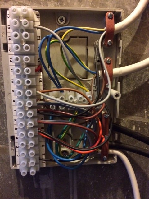
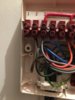
The SCR receiver shown in your first photo should be decommissioned. It cannot just be disconnected, otherwise the heating will be 'open circuit' and will not work. You need to trace the white cable shown in your first photo of the SCR receiver back to its origin at the wiring centre. Unfortunately not all wiring centres are the same and / or installed the same and I can't see the wires clearly enough in the photo to follow them with certainty to tell you which they are.

When you have found the other end of the cable, note where the Grey and Black wires are connected. Now disconnect all four cores of the cable and remove it from the wiring centre. Then insert a wire link between the two terminals where the Grey and Black wires came from thus joining them together. The SCR receiver backplate and the cable to it can then be discarded.

For future reference it is best if you start your own new post rather than tag it on the end of someone else's, doing so means that it could easily missed by most. This is also called hijacking and is against the forum rules. Don't start another one now though, or you will have two threads going on the same topic, which gets very confusing, and is also against the rules.;)

EDIT:

Sorry, I didn't comment on:
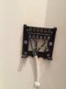
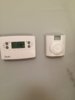
I would like the wall mounted thermostat..... (photo 3 below) to be disconnected.

I didn't mention it, because it won't have any wires connected to it. It is linked by radio signal to the SCR and is battery operated, so once the Hive is up and running, just remove it.
 
Last edited:
Stem - thanks so much for your reply, it is super helpful and apologies for my novice approach to the [lack of] forum etiquette. As you suggest, I won't start anything new on same subject.

Just a final question if you don't mind - the grey and the black that need to be removed from the wiring centre are in the bottom side of ports 2 and 3 (photo attached) (also two wires into port 2, I assume the brown stays where it is). When you say wire link where the grey and black were removed from - do you simply mean attach a single short length of wire between those two ports (in this case 2 and 3?).

Again, many thanks,

Scott
 

Attachments

  • IMG_0358.JPG
    IMG_0358.JPG
    187.6 KB · Views: 732
Yes, you are on the right lines. All four wires from the thermostat cable, plus the earth would be removed, and that's all. Any other wires will still be required.

I thought the terminals for the black and grey would be 2 and 3, but couldn't be see well enough in the photo to be sure so thanks for that clarification.

Once you have removed the wires, it looks that you will be left with just a brown in 2, and a red in the top of 3. If so, then you can either insert a wire link between 2 and 3, or instead just move the remaining brown wire from 2 into 3 so that it connects with the red, and so electrically achieves the same thing.
 
Thank you - I have done all of that and the receiver/boiler seem to be talking to each other, certainly the boiler fires up. However, the CH isn't actually coming on and the boiler is displaying the attached code intermittently with temperature (it is a Worcester Bosch 30CDi. I think I am very nearly there - am I?

Many thanks
Scott
 
Now with the error code
 

Attachments

  • IMG_0359.JPG
    IMG_0359.JPG
    93.4 KB · Views: 754
Yes sounds good to me, but I'm a sparkie, so not really au fait with the boiler workings, but I think that's normal when power has been interrupted. See excerpt from the boiler manual below. You probably just need to be patient.

Capture.JPG
 
You are right - boiler has restarted and all working. You are a gent, can't thank you enough for this help, much appreciated. S.
 

DIYnot Local

Staff member

If you need to find a tradesperson to get your job done, please try our local search below, or if you are doing it yourself you can find suppliers local to you.

Select the supplier or trade you require, enter your location to begin your search.


Are you a trade or supplier? You can create your listing free at DIYnot Local

 
Sponsored Links
Back
Top