Wiring multiple sockets on fused spur - what is the electrician calculating?

Joined
10 Mar 2019
Messages
27
Reaction score
1
Country
United Kingdom
Hi,

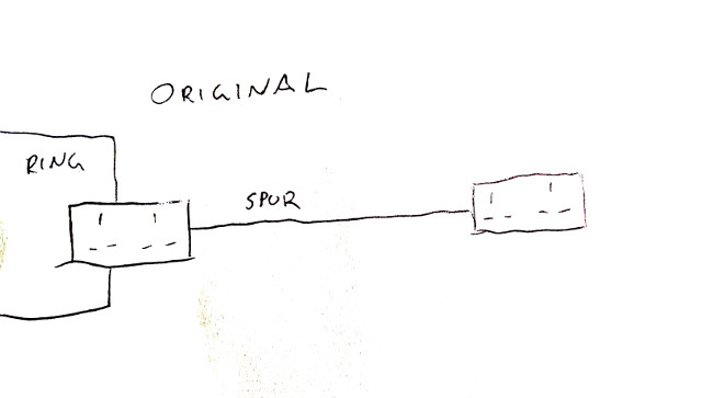
My house was built last year and came with a double socket in the garage, on a spur connected through the wall to the kitchen (see "original" below).


I wanted to add more sockets to the garage for convenience, but don't need any extra power, so I'm limiting the whole garage to 13A through an FCU (originally I had a breaker as per an earlier post, but the electrician didn't like it so I went for the more standard FCU).

I've added 7 sockets (I know its a lot, but they're in convenient places) but I've only drawn 4 in the diagrams for simplicity. All wiring, including before/after FCU, is 2.5mm T&E.

I had an electrician look at what I've done. However he did not like how I had wired up the sockets, see "attempt #1" below, which was using multiple junction boxes branching off in a non-radial arrangement. I believed that the 13A FCU meant I could wire it up however I like, but he said it had to be radial.


So I went for "attempt #2" below, which is fully radial. The whole length of the spur is as a result almost 30m, which means I think I could see up to 7V voltage drop based on 2.5mm T&E ratings (0.018 x 13A x 30m = 7V). But that should be within limits, I think.


However, the electrician now says he is concerned that because "the fused spur is fed radial from a socket & not wired directly to form part of the ring final" then "the load at the first part of the circuit from skt to spur could exceed the rating of the cable supplying it", and he needs to go and do some calculations.

This seems really odd to me. The load to the FCU will be the same as the load after it, right? And a single spur with double socket or FCU off one point in the ring is totally standard, isn't it?

So my two questions for any electricians who might read this:

1) Was he right that I had to change the wiring on this fused spur from branching junction boxes to completely radial.
2) Why would there now be a problem with load between the ring and the FCU? What is he actually needing to calculate here?

Thanks in advance for any input.
 
Last edited:
Sponsored Links
1) No.
2) There isn't a problem. It is protected by the 13A fuse.

Your attempt #1 IS a radial. Although I agree about the JBs. You could have wired from socket to socket.
 
Thanks for the reply.

When you say "socket to socket" do you mean I could still have branched out from them (that is one socket then splits to two more sockets etc).

Because the reason I was branching, rather than going in a single line, was to reduce the length of the cable. Now I've gone socket to socket ("attempt 2") the length from first to last is almost 30m.
 
Any arrangement, really. Perhaps one JB at the start.

upload_2019-10-3_14-39-35.png
 
Sponsored Links
That would then be known as a lollypop (sic) circut ( seriously that is the name )
Some people call it a lollipop circuit, but plenty don't. Nowhere is it officially designated as that.

The NICEIC refer to it as a "hybrid radial/ring" arrangement.
 
Thanks for the explanation, I must have misunderstood what radial means - I thought from what he was saying that everything had to be in a single line.

That is a pain, because I've largely rewired everything for apparently no reason!

On to the second point, the FCU itself. I've got a bit more clarification from the electrician. He says:

"The FCU needs to be on the ring final & not part of the radial circuit" because "if there is a single cable wired to the FCU from the back of a socket in the house" then "that cable will be unprotected to sustained overload & long term damage despite being protected by a limiting fuse. Fuses work fine in a short circuit but in an over load can take as much as 1.8 to 2 times there rated current & there have been cases where this has been even higher."

For me this has two separate issues (I'm numbering on from the first post!)

3) How can it make any difference whether the FCU is on the ring final or on the radial spur? Because he seems to be saying that if it is on the spur then the cable between the spur point on the ring and the feed to the FCU will be under higher load than the cable on the load side of the FCU. But that to me seems to contradict basic electronics for a series circuit - what am I missing here?

4) I'm sure he's right that cables can be subjected to higher loads over the long term than the fuse rating. However, a 13A FCU on a spur is as far as I know a very standard thing. In fact it replaced a double socket, which could have led to greater load than 13A, even over the long term, and that is standard on all the new houses round here. This doesn't seem like something that should require calculations?

Again appreciate the input.
 
"The FCU needs to be on the ring final & not part of the radial circuit" because "if there is a single cable wired to the FCU from the back of a socket in the house" then "that cable will be unprotected to sustained overload & long term damage despite being protected by a limiting fuse. Fuses work fine in a short circuit but in an over load can take as much as 1.8 to 2 times there rated current & there have been cases where this has been even higher."
Not so. As I said, It is protected by the 13A fuse so cannot be overloaded. It is, after all, the same size as the cable after the FCU.

3) How can it make any difference whether the FCU is on the ring final or on the radial spur? Because he seems to be saying that the cable between the spur point on the ring and the feed to the FCU will be under higher load than the cable on the load side of the FCU. But that to me seems to contradict basic electronics for a series circuit - what am I missing here?
Nothing. You are correct. It is obvious isn't it?
Anyway, 2.5mm² cable (assuming it is that) can carry 27A. A 13A fuse cannot.

4) I'm sure he's right that cables can be subjected to higher loads over the long term than the fuse rating. However, a 13A FCU on a spur is as far as I know a very standard thing. In fact it replaced a double socket, which could have led to greater load than 13A, even over the long term, and that is standard on all the new houses round here. This doesn't seem like something that should require calculations?.
Exactly.
 
I thought from what he was saying that everything had to be in a single line.
Presumably that is what he was suggesting, and it's a view I've heard expressed on numerous occasions. That doesn't make it a valid or correct view, however. In fact it can be beneficial to centre-feed e.g. to reduce the volt drop.
 
... which means I think I could see up to 7V voltage drop based on 2.5mm T&E ratings (0.018 x 13A x 30m = 7V). But that should be within limits, I think.
Actually, what theoretically matters is the VD in the entire circuit (back to the CU), not just in the cable from the FCU. However, I imagine that even that would be within the 5% (11.5V) guideline (which is only a guideline, not a 'requirement).

Furthermore, don't forget that the worst-case scenario (for which you have calculated the VD in the 30m of new cable) only occurs if the entire 13A load is at the very end of the 30m cable run.

Kind Regards, John
 
Thanks for the explanation, I must have misunderstood what radial means - I thought from what he was saying that everything had to be in a single line.
No, as has been said, what you have is a 'radial with branches', which is still a radial circuit.

The only common alternative to a radial circuit is a 'ring (final) circuit' and that is an (unbranching) radial with a second connection back to the CU from the final socket in the run. Any branches from a ring final are called 'spurs' (which can be fused, like yours, or unfused - but the latter can generally only supply one socket).

As has been said, I think you need an electrician who understands what he is talking about m- you appear to understand more than he does!

Kind Regards, John
 
Thanks everyone for your input, it's very helpful.

It's a shame because he states on his card he is an NIC EIC approved contractor, he seems a nice guy and I don't get the impression he's trying to rip me off (he's not asking for extra payment for this). It's also not as though he's being a cowboy and trying to do something unsafe.

Normally I would try to prioritise advice from a qualified tradesman in front of me over advice on internet forums, but it seems clear that he's in the wrong. I'm worried now about some of the other electrical advice he's given me! I might ask in another thread.

Regarding the layout I could do the lollipop/hybrid arrangement, but I think I'll go back and add a few branches in order to reduce the end-to-end length and the worst-case voltage drop.
 
It's a shame because he states on his card he is an NIC EIC approved contractor, he seems a nice guy and I don't get the impression he's trying to rip me off (he's not asking for extra payment for this). It's also not as though he's being a cowboy and trying to do something unsafe.
Fair enough - that's not as bad as some, then! As flameport implies, it could well be that he has limited understanding of basic principles which would enable him to think a bit more laterally - so instead 'plays safe' by only doing things in the manner of 'examples' in the books etc. However, that means that he is being 'over-cautious', not in any way 'unsafe' in what he is saying.
Normally I would try to prioritise advice from a qualified tradesman in front of me over advice on internet forums, but it seems clear that he's in the wrong. I'm worried now about some of the other electrical advice he's given me! I might ask in another thread.
Yes, I would never suggest that anyone should given greater weight to advice from an internet forum over that obtained from a real professional/tradesman. However, although it's impossible to 'prove' it, I'm sure that what you have been told/advised here is correct and, unfortunately. much more correct than what your electrician has said.
Regarding the layout I could do the lollipop/hybrid arrangement, but I think I'll go back and add a few branches in order to reduce the end-to-end length and the worst-case voltage drop.
There's no harm in doing that but, to be frank, you will not have any problems with voltage drop even if you don't.

This 'voltage drop' business is all a bit silly given the wide variation in supply voltages that is permitted. The chances are that you probably usually have a supply voltage of 240V or more, but other people could theoretically have one below 220V (216.2V is theoretically the lowest permitted). If that's the case, then you could have over 20V voltage drop in your circuit and still be no worse off (in terms of voltage getting to the loads in your garage) than some other people, even if they had almost no VD in their circuits.

Kind Regards, John
 

DIYnot Local

Staff member

If you need to find a tradesperson to get your job done, please try our local search below, or if you are doing it yourself you can find suppliers local to you.

Select the supplier or trade you require, enter your location to begin your search.


Are you a trade or supplier? You can create your listing free at DIYnot Local

 
Sponsored Links
Back
Top