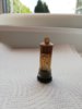
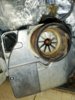
Looking at your picture there.....it's an Inter B9 burner - a good bit of kit.
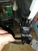
Sitting on top of the BFP41L3 pump is the notorious solenoid coil. Above that is the photocell, the mounting flange of which is held on with 2 screws. Leave the screws alone, the photocell just unplugs but it has a notch to give correct orientation in the flange.
Bottom right white screw is the one that's turned to open or close the air door - leave that alone as it will upset the CO2 ratio if you turn it.
The control box (Satronic 832 I think) controls the timing of the purge and the spark production time.
An electric motor directly couples to the oil pump and has a draught fan on its other end.
The igniter is below the control box.
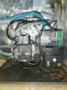
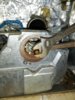
To access the nozzle the burner has to be removed, but first close off the oil supply, disconnect the braided flexible pipe and disconnect the blue sheathed wire. That only goes one way too.
The burner is held into the firebox by two screws at the top.
If you venture that far, the burner comes away leaving a blast tube visible and the nozzle within that.....the nozzle sprays the kero, and its ignited by two electrodes that spark. The electrodes are behind the nozzle but air blows the spark into the kero spray. The nozzle unscrews (17mm spanner) but its holder needs to be supported with another spanner as you do so.
Its good to know how oil burners actually work.....with this one, as soon as you switch it on:
Motor starts, ignition starts and runs for a few seconds but no oil is introduced (the purge of fresh air into the system)
After a few secs the oil is turned on by the solenoid coil, the spray is ignited by the ignition electrodes
The photocell sees the burning flame and turns the ignition off - the burning continues. If the photocell is faulty the burner shuts down after a few more seconds.
I hope this gives you a few clues about how the thing works, but an oil pressure gauge and FGA is needed to set the thing up.....settings can't be guessed!
John
")