Sorry for late reply sparkies
")
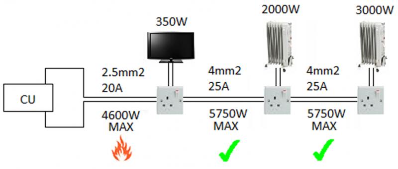
(Diagram was based on 230V supply)
Also - 4mm² T+E is capable of carrying a maximum of 37A (depending on the installation method) so is normally on a 32A mcb.
Depending on the installation method?? I assume you mean clipped?? I read 4mm² was 25A? Is there anywhere on the net I can get exact figures?
Installation method includes clipped direct, in metallic conduit, in non-metallic conduit, in metallic trunking, in non-metallic trunking, on cable tray, in thermal insulation, buried in the ground, and many more besides.
Installation method can reduce how much current a cable can safely carry by up to 50%
So whilst 4.0mm² 6242Y cable can carry 37A in optimum conditions, it would only be able to carry 18.5A in the worst case conditions.
All the current carrying capacities, and information about installation methods, derating factors and much more can be found
here
Now a 32A mcb would be useless in this diagram as it would not protect the 2.5mm² cable, only the 4mm².
Correct, and for that reason it is not permitted by BS7671
Your flames under the 2.5mm² cable hopefully would not happen because the 20A mcb, which should have been used, would disconnect the supply.
Therefore, you'd never get the benefit of the full capacity of the 4mm² cable.
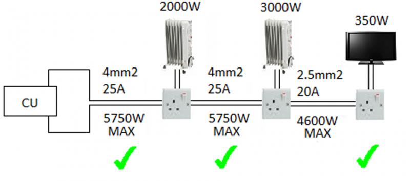
So basically what I'm saying is, you can't uprate the circuitry eg. 2.5mm² to 4mm². Is this correct? It has to be consistent yep?
Correct. You have to rate the protection to the weakest part of the circuit.
You can, and indeed may need to increase the conductor size if there is a long run and volts drop becomes too great for the cable, or, if the cable runs through thermal insulation for part of the circuit, you may want to increase the size of that cable to maintain the overall circuit capacity.
Yeah, I was a bit confused because 2.5 is rated at a max of 26A in ideal conditions.
I thought 2.5mm was minimum of 18.5 to 20A?? How's it gotten to 26A?
It's always been 13A to 26A depending on the installation method.
...but no one would design a circuit like your first diagram.
It's merely to get an answer to my question and what could be easier than showing someone a diagram

Given that you are also curious about cable installation routes....
What re you planning?
A career in electrics?
I think you've still got quite a bit of learning to do yet my friend.....


 .
.") . RF Lighting thanks very much! Very informative; clears everything up.
. RF Lighting thanks very much! Very informative; clears everything up.