

Hi,
I'm currently having issues with my central heating system (oil boiler) following replacement of an old programmable controller and room thermostat. I have some electrical knowledge as an electrician but not specific to heating and controls.
So the basics; I have an oil boiler located in the garage, a cylinder in the airing cupboard, with a 2 port valve adjacent the cylinder. I have a two channel programmer located beneath the stair cupboard and a thermostat located in the hall located directly above it.
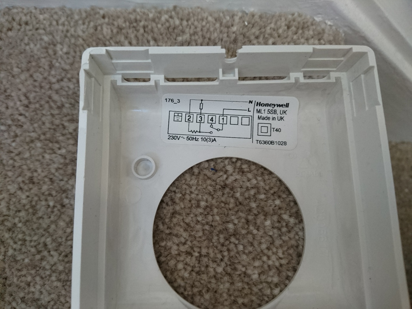
My old stat was malfunctioning on the display so I had to replace it, and none of the existing wiring was labelled or matched the new plate, as the old was original (1980's). the hot water comes on, although not sure it follows the set programme, but the central heating does not come on at all.
I want to know how to identify the cabling and to understand the system a bit more to enable me to re-wire it correctly.
i'll attach some images below to help diagnose my system and the problems.
I'm currently having issues with my central heating system (oil boiler) following replacement of an old programmable controller and room thermostat. I have some electrical knowledge as an electrician but not specific to heating and controls.
So the basics; I have an oil boiler located in the garage, a cylinder in the airing cupboard, with a 2 port valve adjacent the cylinder. I have a two channel programmer located beneath the stair cupboard and a thermostat located in the hall located directly above it.
My old stat was malfunctioning on the display so I had to replace it, and none of the existing wiring was labelled or matched the new plate, as the old was original (1980's). the hot water comes on, although not sure it follows the set programme, but the central heating does not come on at all.
I want to know how to identify the cabling and to understand the system a bit more to enable me to re-wire it correctly.
i'll attach some images below to help diagnose my system and the problems.
![DSC_1708[1425]](/diy/media/dsc_1708-1425.100555/full?d=1510524523)
![DSC_1717[1411]](/diy/media/dsc_1717-1411.100556/full?d=1510524523)
![DSC_1718[1424]](/diy/media/dsc_1718-1424.100557/full?d=1510524523)
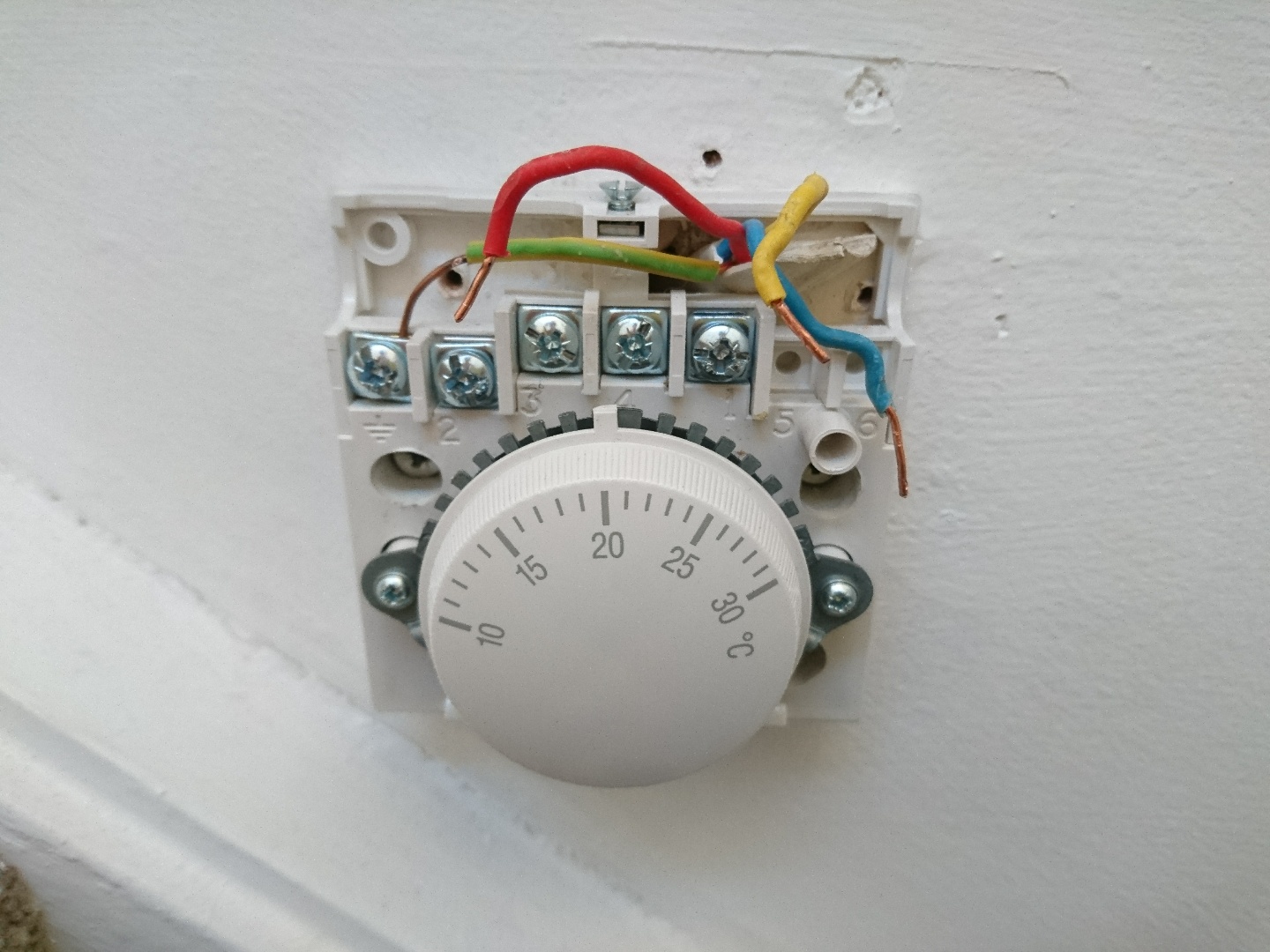
") ) but presumably the conductors will be dependant on what the timer terminal colouring is?
) but presumably the conductors will be dependant on what the timer terminal colouring is?