Nest Thermostat 3rd Gen wiring- converting from Honeywell BDR91 relay box

Joined
5 Dec 2017
Messages
3
Reaction score
0
Country
United Kingdom
Hi

I have a Vaillant ecoTec Pro 28 combi boiler which currently operates with a Honeywell wireless programmer and a Honeywell BDR 91 relay box. I'm thinking of replacing the Honeywell controls with a Nest 3rd Generation Thermostat and trying to determine whether or not i need to get it installed professsionally.
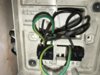
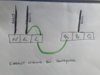
I have looked at the wiring in the BDR91 and note it is wired as follows :

1 Black wire connected to Neutral
1 Black wire connected to Live (middle in photo below)
1 Black wire connected to B
1 Green/Yellow wire connected from Live (middle) to Live (right)
1 Green/Yellow wire connected from Live (right) to A

(I assume that although the electrician that originally installed the Boiler and Honeywell system used Green/Yellow wiring, they are not actually earth cables and that he should have covered them with the proper colour tape so that they could be correctly identified).

The 3 black wires will i assume simply connect to the Nest Heatlink unit as follows

Honeywell (Black) Neutral - Neutral
Honeywell (Black) Live - Live
Honeywell (Black) A - 3

What action is required regarding the Green/Yellow wires in the Honeywell ? How do they convert to the Nest unit? I was under the impression that a wire would be required at connection 2 on the Nest.

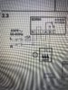
I'd be grateful for any advice. I've included a photo of the original BDR91 wiring diagram, one of the actual wiring in mine and a sketch in case the photo doesnt show clearly where each wire is connected.

I will probably still get an professional installation as i'm guessing they would rewire it directly from the boiler using the correct cables/colours but in the meantime i'd like to try and get my head arround what the correct wiring should look like.

Thanks

Harry
 

Attachments

  • IMG_5665.JPG
    IMG_5665.JPG
    245.3 KB · Views: 785
  • IMG_5668.JPG
    IMG_5668.JPG
    632.5 KB · Views: 766
  • IMG_5669.JPG
    IMG_5669.JPG
    174.7 KB · Views: 568
Sponsored Links
What a mess.

The wiring diagram is in the nest installation manual. If the wiring is this sh¦t here it is likely to be just as bad elsewhere I would recommend calling in a professional heating engineer to install it properly, for a start the upper green and yellow link between the 2 L terminals isn't even needed.
 
Thanks for your reply. I did have a look at the Nest installation manual on their web site which was how i was able to determine where i thought the black wires would go n the Nest Heatlink unit. I agree with you though that the wiring in the Honeywell is awful. My concern is that it was a professional heating engineer (recommended by Phoenix Gas) that did the work, so before i get another so called "professional" in, I'd rather get an idea of what the correct wiring should be. Hopefully they will wire direct from the boiler as its right beside the Honeywell relay box but just in case they attempt to do a rewire from the relay box, i want to know if they've done it right.
 
This is how my honeywell is connected.

Left to Right
- N- Neutral supply
- L- live Supply ( to power the unit)
- L to L is not needed (hes linked it so the first live gives power to the second live) but Im sure it already does that
- Second L to A is linked so it’s constant
- B is connected to switch for boiler

If you have a multimeter, if you take the L-L out and test if the second L still has power, that would comfirm my theory that it doesn’t have to be there.

Hope this helps.
 
Sponsored Links
Just to add, I’d suggest getting some insulating tape in various colours and identify each wire using a sensible colour tape as you disconnect them from the old unit.
 
I'm not as much of an expert as some on Nest here, but I do have a honywell programmer and BD91 relay. And it is connected to a combi through connections at A and B. Mine does not have the live bridge wire to term A. It looks like your combi is configured to operate at 230V for the stat so if it is working properly, the BD91, I would replicate that set up in the Nest.

I agree with other comments, that wiring is terrible a long way from professional. Lots of conductor showing, use of a earth coloured cable for live conductors, no identification marks on the black wires......
 
Thanks for all your replies. I've definately got a better handle on what the wiring should look like. The Nest website does provide a wiring plan relating to a 230v combi boiler (photo attached) which seems to confirm the information you all have given me. I'll think my best course of action is to perhaps get it professionally installed as I cant be certain but it looks as though the wiring used in the Honeywell is stranded and its my understanding that the Nest doesnt support this type of wiring.

I think in the circumstances it will make more sense, getting him to just rewire it directly from the boiler. so at least i'll have it correctly wired/labelled making any future changes easier. If it hadnt beened for the stranded wiring, i think i may have attempted it myself as it looks pretty straight forward, after you guys have clarified things for me. Thanks again
 

Attachments

  • IMG_5673.JPG
    IMG_5673.JPG
    585.2 KB · Views: 510
Thanks for all your replies. I've definately got a better handle on what the wiring should look like. The Nest website does provide a wiring plan relating to a 230v combi boiler (photo attached) which seems to confirm the information you all have given me. I'll think my best course of action is to perhaps get it professionally installed as I cant be certain but it looks as though the wiring used in the Honeywell is stranded and its my understanding that the Nest doesnt support this type of wiring.

I think in the circumstances it will make more sense, getting him to just rewire it directly from the boiler. so at least i'll have it correctly wired/labelled making any future changes easier. If it hadnt beened for the stranded wiring, i think i may have attempted it myself as it looks pretty straight forward, after you guys have clarified things for me. Thanks again

Yes, that is the wiring diagram. 230v combi. Looks relatively straightforward map from the BD91. If you have some experience and can use a multimeter etc. you should use some colour sleeving on those black cables at the very least to identify as you pull them out.

Your wiring can be tidied up by someone with more attention to detail and experience. It is virtually a 1 to 1 match across that 230v nest diagram. The use of earth colour insulated cable for the jumper / bridge links should be replaced with brown or another suitable if required on the nest i.e. between L and 2.

Cables should be carefully trimmed and inserted fully into contacts with no copper strands showing.

If any of this is unfamiliar to you, you have suggested it maybe you should pay someone to do it. It will not be much work. The wiring is all 230v, getting things wrong could kill a component like relay box or boiler pcb, or worse, yourself, if you are not confident in what you are doing.

Most important basics are to isolate all supply while doing and prove no conductors are live (even after isolating) before touching. So you need a multi meter
 

DIYnot Local

Staff member

If you need to find a tradesperson to get your job done, please try our local search below, or if you are doing it yourself you can find suppliers local to you.

Select the supplier or trade you require, enter your location to begin your search.


Are you a trade or supplier? You can create your listing free at DIYnot Local

 
Sponsored Links
Back
Top