Joined
6 Feb 2007
Messages
77
Reaction score
1
Location
Swansea
Country
United Kingdom
Almost a year ago I was trying to resolve a few issues with our underfloor - see orignal thread in plumbing here:

https://www.diynot.com/diy/threads/underfloor-heating-a-couple-of-issues.493454/

The meachancal side is fairly under control (!) now nut the control side - electrically, is still having some issues.

Heating is UFH throughout property, on both floors.

There are two manifolds, one on ground floor, one on first floor.

Two wiring centers, and one controller.

Read more: https://www.diynot.com/diy/threads/underfloor-heating-a-couple-of-issues.493454/#ixzz5WGyCB4ao

The summarise the discussion from the other thread:

I noted that despite the room stats all having turned off, and rooms all being at temperature, the downstairs (as far as I knew) pump was still running. Since I had left the pump on setting 3 downstairs I was able to hear it (see mechanical issues i was having and why i had turned it up). I double checked and all stats required turning up to get a click, so they were all off at idle (room temp was satisfied). This should mean downstairs system should not circulate as I understand.

I set the controller to off, then back to auto, and the pump did not then come back on, unless I bumped any of the thermostats upward, as expected.

The stats for each floor seem to all correctly turn on their respective actuators, I checked this last year.

If I knock off all stats upstairs and downstairs, when both pumps were running, the pair both knocked off. But then only bringing a downstairs one back turns both pumps back on. It's not possible as far as I can tell to bring the upstairs pump on by itself. So i think that if upstairs stat calls for heat, but none downstairs is, then we cant get heat upstairs by itself, unless downstairs has been on and goes off, at which point, upstairs and downstairs pump stays on.

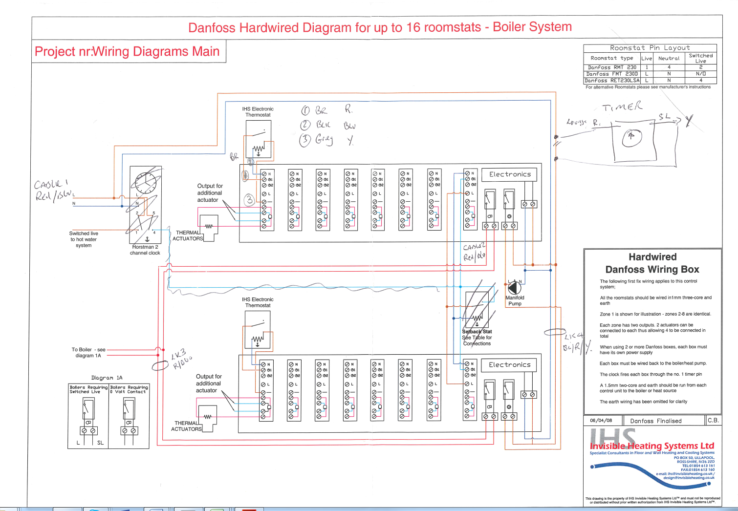
There is a wiring diagram that I dug out of docs on house, but despite it having two wiring centres, it only shows one pump.... So I don't know how that transfers to my system? I do have two wiring centres, but I have two manifolds and two pumps. I'll upload it shortly :)

upload_2017-12-12_14-54-34-png.132651


I know pump had power, (since its been turned up to three and is louder) , it was resonating the wall again, so I can hear it in most of the house, even if it is faintly...

I have attached pdf of the wiring diagram I found and a jpeg. PDF is better quality - as I say, I don't know if its as installed, and I don't know how they handled the second pump, this diagram shows only one pump.

When looking at invisible heats manual, they don't have any system diagrams with two of their manifolds featured, so they never describe a system where zoning a manifold is required - HOWEVER, they do show two port valves in relation to systems with a hot water tank or similar, or radiators and underfloor , so I guess this is similar to having a second manifold.

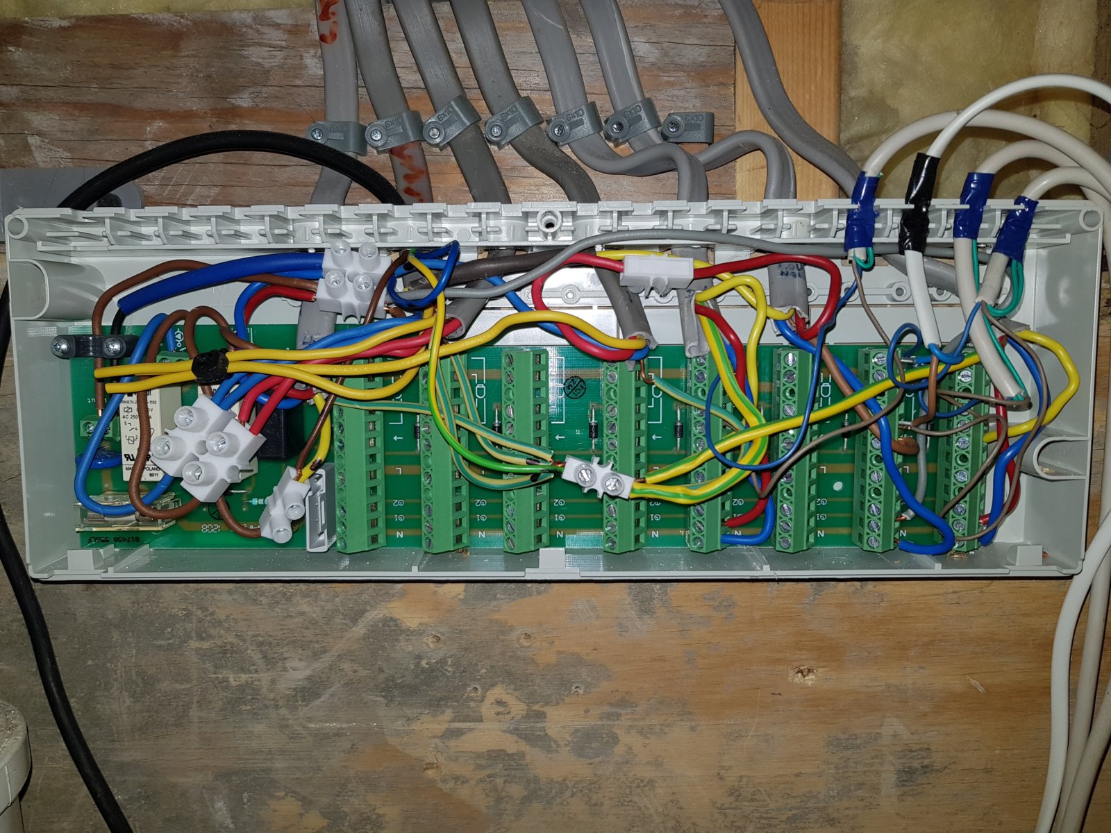
wiring centre image:

4 white wires are actuators, two go to one block as they are driven from one stat in living room.

black cable is pump.

three grey cables furthest right are stats as far as I can tell.

Nothing seems loose or no signs of blown components, at least on this side....

20171204_202700-jpg.132281


The discussion turned to the relationship between controller and zone valves, or between 4 wire actuators and zone valves - which as far as I can tell, I do not have (zone valves that is).

I feels like somehow the wiring of the pumps and relays is incorrect.

Can someone help me please, as right now I must be wasting electrical and heat energy through circulating when i do no want to.


PDF copy of marked wiring diagram is attached in addition to the jpeg - the pdf can be zoomed once open for better clarity.


Read more: https://www.diynot.com/diy/threads/underfloor-heating-a-couple-of-issues.493454/page-2#ixzz5WGtzEK00
 

Attachments

  • 12-12-2017_11-17-25 (1).pdf
    2.3 MB · Views: 324
Sponsored Links
Wow what an absolute mess. Not to mention using the bare earth wire as a switched live. Terrible. I would recommend contacting someone competent to work on heating wiring to install it properly, and safely.
 
I would agree, not the best piece of wiring by whoever did it...

I have actually tried to find someone to come and diagnose the system, but I'm finding it challenging - no one is interested, they'd rather install nice new stuff :(

If I can at least have a better diagnosis I might be able to get someone in to confirm and re mediate :)
 
I think you're going to have to do a bit of detective work here, and work out how it's actually wired.
From the photo, I can't see how the right hand grey cable is wired, but the third from right looks about right. The second from right is not right for a room stat - one core is linked through to the 4th from right grey cable.
On the upside, I think the "electronics" are exceedingly simple - my guess is that those diodes (the small black cylinders with silver end band located next to each zone connection) simply "adds" the zones together to drive the relays. I suspect that on the back of the board, all there would be to see are some tracks running up-down to link the switched live from each stat to the corresponding actuator output terminals.

If you can manage to work out how it's wired, then the fault is likely to be obvious.
...

Now I've had another look, the pump live has a connection to the yellow of the left hand grey cable. I don't think this should be needed if this is the only wiring centre for the zones run from this pump. From reading your description, this is the downstairs wiring centre - downstairs zones and a separate pump from the upstairs zones ? If that is the case, and assuming it's connected to the pump circuit in the other wiring centre, then this connection should not be there - it's basically meaning that if ANY zone is one then both pumps will run.
So one quick test would be to disconnect that yellow wire from the chock block (get hold of some more chock block and park the yellow cable in that). I suspect that this might fix the "upstairs-downstairs" linkage problem.

...

Critiquing those wiring centres, the design has (IMO) a number of significant design faults - or in the vernacular, they're cr*p !
The first is that there just isn't enough room to run the wires about. I guess that's in response to customers saying "I don't want big ugly boxes all over" - so they make them smaller and the installers just have to cope.
Then there's no provision for connecting the earths. That IMO is unforgivable - there really ought to be at least 2 earths per zone terminal strip plus others at the relay end.
Then niggles like having a pair of terminals for the pump - but no spare connections for the live feed to one of them, and no spare neutral for the pump. Hence the installer having to use chock block to make some of the connections.
All in all, it really needs a separate junction box to provide all the connections missing from the wiring centre :whistle:
 
Sponsored Links
The description of operation would suggest that someone has wired it substantially as shown on the diagram, with the two wiring centres linked for a single pump, but then wired in a second pump somewhere.
If each wiring centre has it's own pump, then each pump needs to be wired to one wiring centre only, and the link wires shown on the diagram for the pump removed.

Basically following the wiring diagram for the top one, but deleting the orange wire linking the two (starting from just under the words 'manifold pump' on the diagram).
Second pump wired to the second wiring centre in the same way as the first one. Boiler outputs still linked as shown in red.

The timer drawn in on the right appears to cut power to the entire system, which is not the correct method of operation. Suggest that is deleted and the wires linked as originally intended, shoving a timer in there has no useful purpose.
Temperature control should be via the room thermostats only, the system remaining powered at all times even when no heat is required. With all thermostats satisfied / off, there should be no pump running and no demand from the boiler either.

The wiring in the photo is a shambles, and needs to be completely redone. Would be useful to mount the box on the wall the right way up as well.
 
The timer drawn in on the right appears to cut power to the entire system, which is not the correct method of operation.
It's the only realistic way of doing it - unless you have stats with a setback function (as also shown as an example in the diagram). It's how nearly all systems (or at least, those without fancy programmable stats) work.
 
I think you're going to have to do a bit of detective work here, and work out how it's actually wired.
From the photo, I can't see how the right hand grey cable is wired, but the third from right looks about right. The second from right is not right for a room stat - one core is linked through to the 4th from right grey cable.
On the upside, I think the "electronics" are exceedingly simple - my guess is that those diodes (the small black cylinders with silver end band located next to each zone connection) simply "adds" the zones together to drive the relays. I suspect that on the back of the board, all there would be to see are some tracks running up-down to link the switched live from each stat to the corresponding actuator output terminals.

If you can manage to work out how it's wired, then the fault is likely to be obvious.
...

Now I've had another look, the pump live has a connection to the yellow of the left hand grey cable. I don't think this should be needed if this is the only wiring centre for the zones run from this pump. From reading your description, this is the downstairs wiring centre - downstairs zones and a separate pump from the upstairs zones ? If that is the case, and assuming it's connected to the pump circuit in the other wiring centre, then this connection should not be there - it's basically meaning that if ANY zone is one then both pumps will run.
So one quick test would be to disconnect that yellow wire from the chock block (get hold of some more chock block and park the yellow cable in that). I suspect that this might fix the "upstairs-downstairs" linkage problem.

...

Critiquing those wiring centres, the design has (IMO) a number of significant design faults - or in the vernacular, they're cr*p !
The first is that there just isn't enough room to run the wires about. I guess that's in response to customers saying "I don't want big ugly boxes all over" - so they make them smaller and the installers just have to cope.
Then there's no provision for connecting the earths. That IMO is unforgivable - there really ought to be at least 2 earths per zone terminal strip plus others at the relay end.
Then niggles like having a pair of terminals for the pump - but no spare connections for the live feed to one of them, and no spare neutral for the pump. Hence the installer having to use chock block to make some of the connections.
All in all, it really needs a separate junction box to provide all the connections missing from the wiring centre :whistle:


Simon,

Thanks for taking the time to try and assist. I follow you logic on the pump wire, and I think this is a good line of enquiry, I will certainly try and do this.

With regard to the first and second wires from the right, they are the wires going to the actuators - so where two wires are in one connection, is where one room stat is driving two circuits - the lounge uses one circuit, plus half the circuit which covers the hallway. I think, now I look at the wiring diagram again, they should have used connections 1 and 4 for one actuator and connections 2 and 3 for the additional actuator, when driving two from one room stat...

upload_2018-11-9_6-55-28.png


I would agree, there simply isn't enough room in these boxes to make it EASY to make it neat, the main wiring, being stiff single conductor, doesnt lend itself to neat routing, if you cant spread it out and have the room to manipulate it.

It does need a few extra neutral and terminals to make it a whole lot neater!

To clarify the other comment on timers - the timer is actually a Honeywell CM67 controller, with room sensor, so in the instance of a failure of the stat in living area, it will limit the system making the room super hot - the CM67 is set to cut off heating at about 28C, so it never limits the house under normal circumstances. But it is set for on and off periods (well, periods where the CM67 stat limits how much heating does go on) and also can be used for holiday periods, and such like.


One thing I have noticed, is that I have 4 wire actustors, but none of the second pairs of wires are used. I know its possible to use thes to drive boiler/pump control - but I assume this is usually only done in single circuit or simpler systems?

I have attached below the wiring center from upstairs in case this helps.

20171212_235550.jpg
 
In my previous message, I was only counting the grey wires (the flat twin+earth and 3core+earth ones).
Now we can see the other wiring centre, it gets even more "interesting" :eek:
It looks very much like that link cable powers the upstairs system - so upstairs is only powered on when downstairs is running o_O And it's held on (hard to see, but it looks like the upstairs pump relay also powers it) as long as any upstairs zone is on - hence why the downstairs pump is running when it doesn't need to.

So, nothing on downstairs - nothing works upstairs.
Downstairs on - pumps run, upstairs zones work normally.
Any upstairs zone on - pumps won't turn off, hence why you're hearing the downstairs pump running when you wouldn't expect it to.

Given the generally "untidy" installation and wiring faults, I'd be just pulling them out and redoing them - hopefully there's some spare length in the cables and/or the boxes can be moved a bit to make some spare. And as Flameport says, put them the right way up !

The correct way to wire it would be :
  • Power to power terminals of the downstairs WC (wiring centre, not toilet :whistle:), using that link cable (red & blue cores) to take it to upstairs WC.
  • Use a spare zone connection for the programmer/timer. Take it's supply from the L&N terminals, and it's output to the "timer 1" terminal. Connect the yellow core of the link cable to a timer 1 terminal to take this signal upstairs.
  • Boiler connections as they are (I think) - use two cores of the cables across the boiler control relay of each WC, so the relays are simply in parallel.
  • Connect each pump only to it's own WC - live supply to one terminal of pump relay, other terminal to brown wire of pump, blue wire of pump to neutral.
  • Connect each room stat to "timer 1" (L), N, and the "arrow" symbol for the switched live from the stat. Electrically I think you'll find that this is commoned to the next two terminals down (actuator connections), and the bottom two are commoned to neutral (so a source of spare neutral connections :sneaky:

The timer 2 terminals won't be used in your setup, but it's just there as a second switched live so you could (for example) have some zones on one timer and others on another - so where upstairs and downstairs are on one wiring centre, upstairs could have a different schedule using a two channel timer.

As to the actuators, yes they may well have auxiliary switches in them - as you say, as an alternative way of turning on the pump & boiler. Is there a make & model number on them ?
 
umm, some of the actuators are honeywell ones, but rebranded by the company who made the system, they were honeywell M100-BGE-IH, 4 wire.

I have replaced some of them when the plastic bodies have failed, with an equivalent.

The additional wires arent used on any of them as far as i can see.

I am glad you were able to detect from the wiring photo whata seems a diagnosis that matches what I have observed. What a giant cluster f"*k!

Andy
 
I need to go back and take a photo from another angle - as when i looked at my photo again - it look like one of the yellow wires is not connected - is it possible they connected the wrong wires to the wrong locations and left some disconnected by accident?
 
Given the general f-ups and poor workmanship in that installation - who knows what they could have done wrong :rolleyes:
 
Yes, that is the wire end i thought looked disconnected!

I came to wondering - if I have 4 wire actuators everywhere, could I set up the upstairs system to use the actuator end switches, to trigger the boiler and pump, leaving me some extra wires to bring power up from the main power feed downstairs?

I was looking at the diagram again - the right most block, which shows the two wiring centres connected by timer, L and N, what is the purpose of that in the diagram, as each wiring centre has its own L and N according to the diagram (although what it has in reality...)

Looking at actual wiring, i don't have a wire to the timer pin on one box, but there is on the other - is this basically what you were inferring to that the second box is receiving a timer pin signal but as a result of the downstairs system running, rather than the timer pin?

it really is a dogs dinner the more you look :(
 
Sorry, don't have time to go back and look at the diagrams again right now ...
The wiring diagram you posted (with it's hand annotations) is for combining two WCs onto one system with one pump (ie more than 8 zones on one manifold). AIUI, in your system you have two manifolds, independent of each other and each with it's own wiring centre.
Assuming I have that correct, then you effectively wire each manifold independently - ie as a single manifold/single WC system - but with a couple of minor changes :
  • You need to common the boiler relays so that either manifold can turn on the boiler
  • You need to arrange the timer(s) as required for the zones across the two WCs
The first of these is already in place - there's a 2 core cable that goes from one WC to the other, and then onto the boiler.

The second depends on how you want the zones to operate. If you want them all to run off the one timer then use the yellow wire (in the 3 core cable that takes the power between the two WCs) to take the timer control from one WC to the other. The timer (in your case, the wall mounted programmable stat) should connect to the "clock symbol 1" line using one of the spare zone terminal blocks. And if you want to use the same timer, use the yellow wire to take the same signal to the other WC.
 

DIYnot Local

Staff member

If you need to find a tradesperson to get your job done, please try our local search below, or if you are doing it yourself you can find suppliers local to you.

Select the supplier or trade you require, enter your location to begin your search.


Are you a trade or supplier? You can create your listing free at DIYnot Local

 
Sponsored Links
Back
Top