Joined
11 Feb 2019
Messages
10
Reaction score
0
Country
United Kingdom
Hi All,

Does anybody have any experience with wiring up key switch zones on a Honeywell galaxy system? I seem to be stuck with getting this to work.


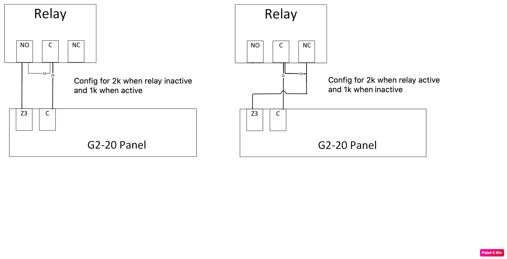
Instead of an actual key switch, I want to use a relay to allow remote setting/un-setting. Looking at the manual, I need to change the resistance of the circuit from 1k to 2k to set the system and then back to 1k to unset.


I have managed to get a working circuit together and testing with a multi-meter, activating/deactivating the relay changes the resistance of the circuit as needed. Now when I connect my circuit into the zone on the rio panel, I measure the resistance of the circuit across zone 3 and com, and the resistance measured is like 6 ohms and then 6.4 ohms when I activate the relay. I’m using the 1k resistors that came with the rio expander. I also tried connecting a 1k resistor directly into the terminals of the rio, I expected to measure 1k of resistance across the terminals, but I don’t, its something silly like 4 or 5 ohms.


I've attached a quick sketch of what ive got cabled up, as you can see when the relay switches from NC to NO, the circuit changed from 1k to 2k. I have also attached the diagram thats in the g2 manual.

4syagVu.png


Any pointers on what I’m doing wrong?


Thanks

Y5RV4td.png
 
Sponsored Links
Use display zones, select the keyswitch zone and press hash to show resistance the panel is measuring on its balanced circuit - displayed on the keypad. You cannot measure resistance with a meter on a powered circuit as your meter is using its own voltage to determine resistance and the panel voltage will mess with this.

Your circuit will work, as the panel allows for small periods of time with incorrect resistances Ie. When the relay contacts are moving. The correct way is with two 1k resistors. Just remove your 2k and replace it with a 1k across NC and common. When the relay is off only 1 resistor is in the circuit. When the relay is on, the normally closed contact opens, so the 2nd resistor is now in the circuit. Two 1k's in series gives 2k.
 
Last edited:
Use display zones, select the keyswitch zone and press hash to show resistance the panel is measuring on its balanced circuit - displayed on the keypad. You cannot measure resistance with a meter on a powered circuit as your meter is using its own voltage to determine resistance and the panel voltage will mess with this.

Your circuit will work, as the panel allows for small periods of time with incorrect resistances Ie. When the relay contacts are moving. The correct way is with two 1k resistors. Just remove your 2k and replace it with a 1k across NC and common. When the relay is off only 1 resistor is in the circuit. When the relay is on, the normally closed contact opens, so the 2nd resistor is now in the circuit. Two 1k's in series gives 2k.

thank you, that explain's the readings!

So i think understand what you're saying re circuit wiring, I've quickly drawn it out, is that what you mean? As when the relay is not energised, the circuit will go via NC on the relay, so 1k in the circuit total? Then, when I turn the relay on, the circuit will go via NO and the other 1k, so 2k total.

Sorry if ive got this wrong, i can do normal PIRs and door contacts, but stuck with this one!
r4G9uvs.png


If ive not drawn what you said correctly, could you draw out what you mean for me please? Template below
2VIcaC5.png
 
No, it's not correct. You're overcomplicating it. I think you're getting confused as you think that you need to use all terminals of the relay when you don't.

Your most recent drawing will work If you totally remove the wire going from common to n/c, leaving the n/c terminal unconnected. This will give 2k when the relay is not energised and 1 k when it is. The choice of using n/o OR n/c depends on needing the 2k when the relay is active or when the relay is inactive. If it doesn't matter to your application, then it's probably best to select the inactive relay state for the longest time that the system will be in that state. Ie. If you are going to have the system set 18hrs a day, then use the option on the left. If the system is going to be unset most of the time, then the one on the right. This reduces the amount of energy required.

 
Last edited:
Sponsored Links
No, it's not correct. You're overcomplicating it. I think you're getting confused as you think that you need to use all terminals of the relay when you don't.

Your most recent drawing will work If you totally remove the wire going from common to n/c, leaving the n/c terminal unconnected. This will give 2k when the relay is not energised and 1 k when it is. The choice of using n/o OR n/c depends on needing the 2k when the relay is active or when the relay is inactive. If it doesn't matter to your application, then it's probably best to select the inactive relay state for the longest time that the system will be in that state. Ie. If you are going to have the system set 18hrs a day, then use the option on the left. If the system is going to be unset most of the time, then the one on the right. This reduces the amount of energy required.


Perfect all working, thank you very much
 

DIYnot Local

Staff member

If you need to find a tradesperson to get your job done, please try our local search below, or if you are doing it yourself you can find suppliers local to you.

Select the supplier or trade you require, enter your location to begin your search.


Are you a trade or supplier? You can create your listing free at DIYnot Local

 
Back
Top