- Joined
- 31 Dec 2009
- Messages
- 124
- Reaction score
- 1
- Country

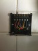
Sure. I'll take a pic shortly. Mind you, nothing's changed in the wiring - it's been the same forever.because you need a HW off signal which is why I asked for a pic of your programmer wiring

Sure. I'll take a pic shortly. Mind you, nothing's changed in the wiring - it's been the same forever.because you need a HW off signal which is why I asked for a pic of your programmer wiring
you would be very surprised how many systems have been wired up wrong and people have used them for years without noticingSure. I'll take a pic shortly. Mind you, nothing's changed in the wiring - it's been the same forever.
The voltage being supplied to the motor is 77V.
OK. I shall have to dig out some wire from the shed (which isn't easy if you've seen my shed currently). In the meantime, I'm back to thinking about the microswitches in the valve. I'm no expert, obviously, but I've watched JW's excellent video on YouTubeyes it has the HW off wired in, as a test, turn off the power, make a temp link between L,1 &4 on the programmer back plate, turn room thermostat to full, do not put the programmer back on, turn the power on and valve should motor to CH only and boiler should come on
well just mark the wires so you know which goes where and join all three together to test, then put them back where they were after you have done the testI shall have to dig out some wire from the shed
OK will do, but I currently have "users" complaining that it's cold so it'll be tomorrow. I've done the manual lever thing to get the CH on for now.well just mark the wires so you know which goes where and join all three together to test, then put them back where they were after you have done the test
Not sure what I'd look for in the microswitch or how I'd test it but I'm suspicious of SW1.
Thanks for that. I'd like to remove the circuit board from the valve but haven't worked out how to do it yet. I know that both switches click when moving the valve manually all the way to the CH only position (SW1 first and then SW2) but I don't suppose that tells me much.Use a meter with a buzzer for continuity testing...
Each one has three terminals, a common terminal (C or COM), a normally open (NO) and a normally closed (NC). With no pressure on its button, check the continuity between C an NC - meter should buzz, press button it should stop.
Connect between C and NC, then press button, it should buzz only whilst pressed.
You can buy replacement microswitches for a few pence on ebay, if you can solder, but there are numerous sizes and types. Measure the ones you have.
I'd like to remove the circuit board from the valve but haven't worked out how to do it yet
I must admit to having lost a bit of momentum. We still have heating because I can activate it manually with the lever so my "users" are happy. I've convinced myself that the problem is with the circuitry on the PCB - whether it's a faulty microswitch or some other component - because I don't see how anything else explains the 77V (or more importantly, the lack of 230V) to the motor when CH is demanded from the default HW position. Even if I tested the microswitches and confirm the fault, I'm unlikely to be able to replace the microswitches (even if I could find exact replacements after desoldering them) without losing the ability to activate the heating in the meantime. Then my "users" wouldn't be happy. So, I suspect I'm looking at a new head/actuator - not sure whether I need a new valve also to match (the metal part). I believe that means draining the system. This would all be outside my comfort zone - once there's water involved, I'm happy to get professionals in.The electrical head part is called the actuator. Over the past few decades I have repaired them numerous times, the spring return type are not easy to work on and can be very unreliable because they are under constant stress, such that always had a spare working item ready to install.
I have since converted to what is called a MOMO valve and actuator. These don't use a spring at all so under much less stress, they motor to each position as required then shut down completely and rather than back and forth, they rotate in complete circles, only in one direction. None the less, I keep a ready to install spare to hand.
Then my "users" wouldn't be happy. So, I suspect I'm looking at a new head/actuator - not sure whether I need a new valve also to match (the metal part). I believe that means draining the system. This would all be outside my comfort zone - once there's water involved, I'm happy to get professionals in
Thanks, but mine's the old style Drayton acl that doesn't have a removable actuator (well not easily) - not like the new style snap-on ones. Drayton tell me that installing the new style actuator instead means draining the system, so I assume that means replacing the actual valve part as well. Did I understand you correctly?The heads/actuators are usually removable, held to the valve by a couple of bolts. They are also usually available as a separate replacement part, to the actual valve. Look up the actuator make and model on ebay. Its always worth having a spare actuator to hand, ready to install, for when it fails. It then gives you the chance to see if the failed item can be repaired.
I have had far more issues with valve actuators, than with any other part of my heating system.
Thanks, but mine's the old style Drayton acl that doesn't have a removable actuator (well not easily) - not like the new style snap-on ones. Drayton tell me that installing the new style actuator instead means draining the system, so I assume that means replacing the actual valve part as well. Did I understand you correctly?
If you need to find a tradesperson to get your job done, please try our local search below, or if you are doing it yourself you can find suppliers local to you.
Select the supplier or trade you require, enter your location to begin your search.
Are you a trade or supplier? You can create your listing free at DIYnot Local
