Upgrading thermostat

Joined
12 Sep 2021
Messages
8
Reaction score
0
Country
United Kingdom
Hi there, I'm upgrading my thermostat from salus rt310 to rt310rf, and want to make sure my wiring is correct. The Thermostat is connected to a 3 channel programmer.

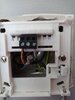
Inside the rt310 are 2 wires brown (live connected to COM), and a grey connected to NO. There is also an unconnected black wire inside - I wonder what that is for?

Could someone have a look at schematic and confirm the correct wiring I need to follow.
I think in the receiver I connect brown to L and COM, the grey to NO, would the black wire go to N?
 

Attachments

  • Screenshot_2021-09-12-13-43-37-040_com.google.android.apps.docs.jpg
    Screenshot_2021-09-12-13-43-37-040_com.google.android.apps.docs.jpg
    121.4 KB · Views: 63
  • IMG_20210911_124417.jpg
    IMG_20210911_124417.jpg
    189.9 KB · Views: 61
Sponsored Links
Thanks, so if I get my multimeter and confirm black and grey are connected on continuity check then I'm good to go?
 
Sponsored Links
from salus rt310 to rt310rf,
One of those is a battery powered wired thermostat, the other is a battery powered wireless thermostat with a 230V wired receiver unit.
The receiver is intended to be located out of sight, typically next to the boiler or similar. Not where an old thermostat was previously located.

The Thermostat is connected to a 3 channel programmer.
The existing thermostat will only have power when the programmer is on.
Installing the receiver unit there will not work, as it requires power permanently.
 
The brown wire in it measures 240v

The reason I want to change thermostat, is because it is in a large hallway next to a frontdoor, the temperature in hall is always lower than the living room and it can heat up too much. I want to put Thermostat in living room and have receiver in position of old Thermostat
 
Last edited:
The old thermostat switches 230V.
It is not powered by 230V, as it doesn't have a neutral connection, and most obviously it also has 2 AA batteries inside.

If you connect the unused black to neutral wherever the other end is, and install the receiver where the old thermostat was, and use the brown for L and the black for N and the grey for switched L, the receiver will have power when the programmer is set for heating on.

When the programmer is off the receiver will have no power. The battery thermostat will then waste the batteries away trying to contact the unpowered receiver.
End result - new batteries required every month.

Given it's a Salus, it will probably unpair itself at regular intervals as well, perhaps every time the programmer switches the heating off.
 
I was hoping this would be straightforward, but maybe not.

I guess I could power the receiver via a separate external mains cable live and neutral, and just use same 2 wires which are for original thermostat.
 
Only if that external cable is connected to the same 3A FCU that supplies the rest of the heating controls.
 
I am sorry I did not realise the limitations of the device. I assumed the thermostat was a timer as well.

All you have to do is install the receiver near the programmer, wiring centre or boiler; wherever the appropriate wiring is.
 

DIYnot Local

Staff member

If you need to find a tradesperson to get your job done, please try our local search below, or if you are doing it yourself you can find suppliers local to you.

Select the supplier or trade you require, enter your location to begin your search.


Are you a trade or supplier? You can create your listing free at DIYnot Local

 
Sponsored Links
Back
Top