help me wire this please

Joined
14 Oct 2023
Messages
189
Reaction score
4
Country
United Kingdom
Hey guys


As some of you know I study at York College. I am working on an assignment exam, Which I need some help with.

Fixed appliances:

  • 12k W electric cooker with induction hub (no socket)
  • 300W extractor over cooker
  • 7 KW electrical central heating and hot water boiler.


Building construction :

  • Outer walls - brick with wood cladding, insulated cavity
  • Inner walls : plasterboard dot and dabbed onto lightweight blockwork
  • Floors: laminate flooring on 50mm concrete seed.
  • Ceiling :plasterboarded through with acess hatch into fully accessible loft void above. Ceiling 2.3m above finished floor level.
  • Loft insulation : this 250mm thick and cables are to be clipped to joist or lay on plasterboard.
Electric supply

  • 230v , TNCS, with ZE and PFC at 0.3 ohms and 0.77ka
  • Amb temp 25 degrees


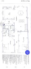
This is for a 2 bedroom bunglow and I need to wire it.


I have decided the accessories will include the below and with FSU for boiler, and cooker:


2 bedrooms –ill put 1 x light in each room. And 3 x double sockets each room

1 onsuite room – so 1x light – no sockets

Small hallway – 1 xlight and 1 double socket and 1 smoke alarm

Bathroom has sections so 2x lights. 0 sockets

Utlity room – 1 x light plus 2 x double sockets

Kitchen 1 xlight. Plus about 7 xdouble sockets and 2 x single sockets.

Large diner and lounge room integrated.. so therefore 2 x lights plus 5 x double sockets


If you think I should add more please let me know.


What will be the best way to wire this ? since theres concrete under laminated flooring, . I am thinking of taking the cables from the consumer unit and take the wire up to the loft clip to joists and drop to the nearest socket for the circuit and then back up the wall clip up the joist and come down again into the next socket. And repeat until the sockets are complete. For the ring curcuits. Take the wire back again same way


In terms of lights can I just lay them over the plastboard? And it doesn’t matter how they go as theres no safe zone etc. is this correct? So in affect I can just go up the consumer unit abover th plasterboard just go in diagnels if I have to get the light and switches?

once Ive done this I will do all the calcs required.


Any advice would be greatly applreciated. I am more than happy to discuss further,.


thanks
 
How many ring final circuits do you propose? Also, with cables in the roof space clipped direct, will these also lay beneath the insulation material?
 
How many ring final circuits do you propose? Also, with cables in the roof space clipped direct, will these also lay beneath the insulation material?

1 radial for cooker
1 radial circuit for boiler
Kitchen has 1 final ring
Rest of the bunglow on 2nd ring
2 lighting circuits due avoid voltage drop.

Yes I believe the joist are smaller therefore would need to be beneath the insulation in the loft.
 
This is the layout of the bungalow. I haven't added all the accessories etc yet on it
 

Attachments

  • Screenshot_20250424_141250_Microsoft 365 (Office).jpg
    Screenshot_20250424_141250_Microsoft 365 (Office).jpg
    127.7 KB · Views: 28
For cables run within or covered by insulation, then a derating factor should be applied. Your current IEE regs will explain this and also tables given. All too often, insulation is ignored, especially on re-wires and then possible problems can occur. I understand your concern about voltage drop and the need for two lighting circuits, but for a small bungalow and a single pendent drop in each room, plus a fixed luminaire in the bathroom, the voltage drop will most probably be well within limits, even using 1mm TW+E. If uprated to 1.5mm to allow for thick insulation, then a single circuit will probably suffice. Domestic lighting loads have significantly decreased since the demise of the tungsten filament lamp.
 
For cables run within or covered by insulation, then a derating factor should be applied. Your current IEE regs will explain this and also tables given. All too often, insulation is ignored, especially on re-wires and then possible problems can occur. I understand your concern about voltage drop and the need for two lighting circuits, but for a small bungalow and a single pendent drop in each room, plus a fixed luminaire in the bathroom, the voltage drop will most probably be well within limits, even using 1mm TW+E. If uprated to 1.5mm to allow for thick insulation, then a single circuit will probably suffice. Domestic lighting loads have significantly decreased since the demise of the tungsten filament lamp.

Hi thanks for that great response.


Everything im doing is for the purpose of my assigment sadly i havent had any experience actually fitting it in.

I have been given a diagram i will need put cables in and add the lengths up and then do cable calcs. The former i can do.

I just need help how to take the cablrs from cu to the accessories. Etc. After I worked out the lengths of cable I'm comfortable in doing cable calcs after that.
 
When chasing cables into the walls, don't forget to cover with capping or run through oval conduit, which is done before any making good, or the cables will be plastered in. Also, full testing before any making good so as to avoid chopping out again if faults found.

 
If working on 20 amp centre and 12 amp even spread, then a ring final has a maximum length of 106 meters to comply with volt drop. If the rooms at 8 foot high, each socket has 10 foot (3m) of cable for the drop. Also, often one needs to drill beams 1/3 from the end, so it depends if you can go over the beams in the loft.

In a freezer, about 4 x size of my house, we needed to put points to use cleaning equipment, and the drops to sockets would have caused a problem, so ring in 6 mm² to junction boxes, and every socket was a spur.

This is where design comes in, and you need to decide how much can go on each ring final. It seems a large bungalow, so likely three ring finals, but then we come to loading, better if the kitchen can draw from more than one ring final, to spread the load, but often people do have a dedicated ring final for the kitchen.

It is not so much what you do, but the reasons you give for what you do. My house has a dedicated supply to the freezers, using SWA cable, so can use RCD sockets, so if one freezer trips the socket don't lose both, and the supply comes from the solar panel inverter with battery, so they will continue to work in a power cut.

This is where one has to think a bit, the inverter has a built-in RCD, but it does not comply with the BS numbers, I know as I have tested, the sockets trip first, but the first one the installers (not me) fitted, they did not know if that was going to be the case. If the inverter had tripped first, then they would have used 10 mA RCD sockets.

In the main we wire by experience not calculations. We know the last house of this size, we were either on the edge with loop impedance or had loads to spare.

As to
ZE and PFC at 0.3 ohms and 0.77ka
The supplier often supplies with a ring, (not ring final) and they can isolate a part of the ring, so the ZE and PFC can vary, with a 100 amp supply to keep within permitted volt drop, one can expect 0.35Ω, and even if you measure 0.25Ω, really one should calculate on 0.35Ω. With a lower supply amps this will vary.
 
When chasing cables into the walls, don't forget to cover with capping or run through oval conduit, which is done before any making good, or the cables will be plastered in. Also, full testing before any making good so as to avoid chopping out again if faults found.

Do you not have complete faith that your cables are undamaged so you can plaster them directly into the wall without capping or conduit.
It is a rare event if ever to find cable is damaged at install if care is taken. Of course if others are about meddling around whilst you first fix you can’t always rely on them not to be rough badgers and swing everything into those cables before they are covered with plaster.
 
For cables run within or covered by insulation, then a derating factor should be applied. Your current IEE regs will explain this and also tables given. All too often, insulation is ignored, especially on re-wires and then possible problems can occur.
Maybe, but the issue usually arises in relation to lighting circuit wiring, and, even for 1mm² cable with the 'very worst' installation method, the CCC is still 8A, therefore fine for a 6A lighting circuit.
I understand your concern about voltage drop and the need for two lighting circuits, but for a small bungalow and a single pendent drop in each room, plus a fixed luminaire in the bathroom, the voltage drop will most probably be well within limits, even using 1mm TW+E.
Agreed - and, in any event, "the limits" are only guidelines.

Kind Regards, John
 
I would add that I prefer at least two poser circuits and two lighting circuits as a minimum built in redundancy.
I recently rented a property near Thurso on the North coast of Scotland and that had one ring final and one lighting circuit. Also the one main switch was an RCD,
Luckily no problems encountered

I would have made it two each power and lighting RCBOs minimum with a radial ignition for the gas heated hot water
 

If you need to find a tradesperson to get your job done, please try our local search below, or if you are doing it yourself you can find suppliers local to you.

Select the supplier or trade you require, enter your location to begin your search.


Are you a trade or supplier? You can create your listing free at DIYnot Local

 
Back
Top