
I don’t want to have separate pir. I’ve bought an extractor fan that’s smart and has ir sensor, Alexa control etc. Once I have kinetic WiFi switch, I’ll link this together in the app only as an automation and it’ll act as pir - having auto lights and auto fan.Just replace switch with Pir , far less to go wrong .

You are using an out of date browser. It may not display this or other websites correctly.
You should upgrade or use an alternative browser.
You should upgrade or use an alternative browser.
Changing pull cord to kinetic WiFi switch
- Thread starter crtz
- Start date
Seems overcomplicated.I don’t want to have separate pir. I’ve bought an extractor fan that’s smart and has ir sensor, Alexa control etc. Once I have kinetic WiFi switch, I’ll link this together in the app only as an automation and it’ll act as pir - having auto lights and auto fan.
Might be but that’s what I’m after. WiFi fan allows to monitor humidity, temp and works great right now. I don’t like pull cord so I’d like to change it to WiFi switch that can be controlled on a wall (kinetic) or in automations.Seems overcomplicated.
Possibly but having seen a couple of offerings I was starting to get confusedI thought my way was simple?
The computer says noCan you get 2 conductors into 1 slot?
Cut the cable going to the light, fit the receiver in the middle, link the switch port, I think, confused myselfPossibly but having seen a couple of offerings I was starting to get confused
The computer says no


Ah just re-read OP.I need a permanent live. Junction box has power in and out already in use. Shall I just use wagos to tap into it? Doesn’t L1 rely on a permanent feed from JB?
I was also thinking about going by permanent feed from isolator switch for bathroom fan. That had permanent live as it comes to isolator.
Any advice appreciated.
If your isolator is 3 pole for L, N, & SL and easy to run a cable to; then a length of 3 core and earth from there to the receiver. BUT that will require additional investigation on how it's been wired beside the Surewire system and how to isolate the existing switch wiring.
Yes that would work, OP's post#13 is effectively the same thing without cutting the existing light cable and easier to restore when the next occupant wants to do away with the confusing automation.Cut the cable going to the light, fit the receiver in the middle, link the switch port, I think, confused myself
So you’re trying to say this would work too? Of course I got l1 confused here.Ah just re-read OP.
If your isolator is 3 pole for L, N, & SL and easy to run a cable to; then a length of 3 core and earth from there to the receiver. BUT that will require additional investigation on how it's been wired beside the Surewire system and how to isolate the existing switch wiring.
Yes that would work, OP's post#13 is effectively the same thing without cutting the existing light cable and easier to restore when the next occupant wants to do away with the confusing automation.
I did take a look at your diagram and I will try it if I won’t get confirmation that below will work too.
Attachments
This is what I mean:So you’re trying to say this would work too? Of course I got l1 confused here.
I did take a look at your diagram and I will try it if I won’t get confirmation that below will work too.
Attachments
You're starting to get mixed upThis is what I mean:
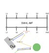
The position of L1 and S1 are fixed in the Surewire by the internal electrics in the white strip between the terminals with Line (Live) going to the switch and Neutral to the light and a Switched Linebetween (I hope I have the numerical designations correct in this pic as I cant read any of the markings but have followed the line sketch)
This
is what you are indicating but you will need to add the link in the Surewire which I've shown in purple (just to make it obvious).
Ultimately you will need to connect to L from S1, E from S1 or L1 & N from L1 which your suggestion achieves.
These are electrically the same and any of the 4 versions are acceptable, only 2 require the link wire:
Thank you. This example makes sense for me. I think the easiest will be to do what I’ve attached. It matches version 1 of 3 examples image. Is this correct?You're starting to get mixed upView attachment 406694
The position of L1 and S1 are fixed in the Surewire by the internal electrics in the white strip between the terminals with Line (Live) going to the switch and Neutral to the light and a Switched Linebetween (I hope I have the numerical designations correct in this pic as I cant read any of the markings but have followed the line sketch)
View attachment 406695
This View attachment 406696
is what you are indicating but you will need to add the link in the Surewire which I've shown in purple (just to make it obvious).
Ultimately you will need to connect to L from S1, E from S1 or L1 & N from L1 which your suggestion achieves.
These are electrically the same and any of the 4 versions are acceptable, only 2 require the link wire:
View attachment 406697
") changed to s2 and l2 as this is exactly as they are for bathroom light. Was going by 1 as it was easier.
changed to s2 and l2 as this is exactly as they are for bathroom light. Was going by 1 as it was easier.Attachments

I don't think that will work as there isnt a live going into the switch connection for one to come outThank you. This example makes sense for me. I think the easiest will be to do what I’ve attached. It matches version 1 of 3 examples image. Is this correct?
Thats what I was thinking

According to the diagram prepared by another user above, it should have live. It’s already supplying live to pull cord, or not?I don't think that will work as there isnt a live going into the switch connection for one to come out
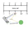
Sorry I've edited this a bit too close but perm L is on S2 and perm N is on L2 the SL parts are redundantI don't think that will work as there isnt a live going into the switch connection for one to come out
just like used here
and as close as dammit to this except I showed it on S1 & L1
Sorry I've edited this a bit too close but perm L is on S2 and perm N is on L2I don't think that will work as there isnt a live going into the switch connection for one to come out
View attachment 406716
just like used hereView attachment 406717
and as close as dammit to this except I showed it on S1 & L1View attachment 406718
DIYnot Local
Staff member
If you need to find a tradesperson to get your job done, please try our local search below, or if you are doing it yourself you can find suppliers local to you.
Select the supplier or trade you require, enter your location to begin your search.
Please select a service and enter a location to continue...
Are you a trade or supplier? You can create your listing free at DIYnot Local
Similar threads
- Replies
- 3
- Views
- 9K
- Replies
- 4
- Views
- 2K