3 amp fused switch and fan isolator.

Joined
27 Jun 2020
Messages
21
Reaction score
1
Country
United Kingdom
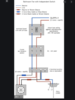
Can someone please tell me if the 3 amp fuse switch or the fan isolator receives the power supply first? They are both situated next to each other and I have discovered that the 3 amp switch neon goes off ( when in the on position) when the fan isolator is turned off. When I turn fan isolator back on, the neon on 3 amp switch then comes back on. This has got me thinking that the supply goes to the fan isolator first. I am in process of installing two mf100t fans in two en suites and the electrician who did the work has left me in a pickle. I’ve managed to determine that the above switches do feed one of the en suites. I wired up a temp light and this turns on and off when the fan isolator feeding the supply is turned on and off. I was hoping that after determining this, that the other en suite would be the same. I tried to find the live feed into the en suite by doing exactly the same as I did in the other but find there is no direct feed in there. If Someone could give me the answer to the 3amp/ fan isolator question, could I then run a spur to the next 3amp switch and fan isolator. Many thanks and sorry for the long winded post.
 
Sponsored Links
Second guessing what you have isn't very wise. You need to do some testing to establish what's what, with a multimeter ,or twin probe voltage tester.
 
Hi, I do have a multi meter and purchased this when I asked the electrician what he had done and what need to be done to resolve the issues. He initially put in 2 core and the decided to put in 3 core. The loft has poor access so all the wiring is currently coming through the ceiling though a removed down light in each en suite so I can easily test anything in the rooms the wires are in. I have the Screwfix multimeters so can you suggest what readings I should be finding when testing this wiring. Thanks.
 
Take one room at a time ,starting with the one you identified the fused switch and isolator for. What cables are present at the ceiling in that room ?
And what circuit is the fused switch and isolator on ,is it a lighting circuit ?
 
Sponsored Links
Hi, thanks for your time. The one that I made a temporary light test on does go back to the area where the 3amp switch and the fan isolator are located. The switches have a spur between them which I should have mentioned and that is why my initial question was which of the two should be getting the supply first. It is on the lighting circuit and initially the wiring for the feed came from the main bathroom which is in the middle of the en suites but further back so when in the loft the cables running from the bathroom to each en-suite ran from the centre bathroom to left and right to the en-suite. Electrician has run 2 core and 3 core from the bathroom and I am trying to determine why and what is live. He has said that he decided to replace the 2 core with 3 core so trying to determine what readings I should be looking for when testing all the wires running from the main bathroom. He cannot remember what he did and the electrics have been certified and passed so there are no issues with anything that is there I just want to test and make safe any wires that may be live. Thanks once again.
 
Two core ?? Do you mean twin and earth cable ? I.E. two core plus earth ?
If so I suspect that would be the supply ( live ,neutral and earth) If the other cable is three core and earth ,that would be a live ,a neutral ,a switched live and an earth and would be a feed for an extractor with timer facility.
 
Hi, yes twin, 2 core and earth and 3 core, as you describe. I noted the fans I was fitting and these do require the 3 core and earth because they need a switch live. I’m just looking to determine what he has connected to the feed from the circuit which he ran from the bathroom. Like I say, both en suite have 2 and 3 core coming from the bathroom where the feed is, so I have all the wires available to test. The one that was wired up to the switches was just cut and I put blocks on the end after stripping the cable. This one is working a light fitting when fitted to the end of the cable and this allows you to turn that temp light on and off and as mentioned, the 3amp switch appears to be being turned off when the fan isolator is turned off. Vice versa, fan switch on, 3amp neon comes back on. It’s 3 core and the brown is live, the grey with blue sleeve is neutral and the black isn’t connected to this temp test as I know it’s a switch live. It seems like the live feed is going to the fan isolator first.
 
Show pics of the wiring at the " 3 amp fused switch " and also the fan isolator.
If you remove the fuse ,does the temporary light still work ?
Why have you not used your multimeter to establish the voltages present ??
 
Hi, removing the fuse makes the light go out. The way it’s wired is that there is a 3 core and earth used going into the fan isolator switch. There is then 3 core and earth used as a link to the 3amp fused switch. There is 3 core and earth then going into the en suite which I have put a temp light on to test the supply. The three core to the fan isolator has live, switch live, neutral and earth connected. The link out to the uses live, switch live, neutral and earth. It goes to the 3amp switch but only live, neutral and earth are connected. The switch live is connected to a terminal block. There is a 3 core and earth used from the 3amp switch and this runs into the en suite. Only live, neutral and earth are used. Switch live connects to the switch live in the terminal block coming out of the fan isolator. He has wired the main bathroom fan the same way. The fan isolator in that also makes the neon on the 3amp switch go out. This is the multimeter. Just need to know the setting I should use to check for a supply and if the lights need to be isolated at the consumer unit.
0F1CB076-10D8-4CBF-9559-BB895577C8FD.jpeg
image.jpg
0F1CB076-10D8-4CBF-9559-BB895577C8FD.jpeg
image.jpg
image.jpg
 
This is why I am confused as to why it is wired this way.
 

Attachments

  • FC4431F8-1E70-413D-B646-BA05129AEE6E.png
    FC4431F8-1E70-413D-B646-BA05129AEE6E.png
    372.6 KB · Views: 4,405
Not sure what you mean or where that comes from. It does not match your description.

In the diagram, the 3-pole switch is completely unnecessary as the FCU will isolate the fan.


I have never seen instructions require a 6A fuse. The circuits in Britain have a 6A circuit so it would be pointless.
Actually the 3A fuse is almost as pointless electrically but an FCU, when used, has to have a fuse in it.
 
It appears from the pics / wiring ,that the 3 pole isolator is feeding the switched FCU .
 
So removing both switches and replacing with this should help? Cheers.
 

Attachments

  • DF608A8D-746D-42EE-AFCB-9BFF41612636.png
    DF608A8D-746D-42EE-AFCB-9BFF41612636.png
    359.9 KB · Views: 650
Yes, you can use that one.

You should still wire it as per my diagram.

You can use the 'out/load' connector to join the two switched live wires, otherwise the fuse will not protect the switched live.
 

DIYnot Local

Staff member

If you need to find a tradesperson to get your job done, please try our local search below, or if you are doing it yourself you can find suppliers local to you.

Select the supplier or trade you require, enter your location to begin your search.


Are you a trade or supplier? You can create your listing free at DIYnot Local

 
Sponsored Links
Back
Top