Anyone good with "electronics" here? didn't notice a sub-forum

Joined
28 Jan 2010
Messages
86
Reaction score
2
Country
United Kingdom
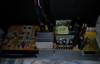
anyone good with Class D amplification? I have an active speaker here, it powers on ok, i must had overdriven it as it did get a bit hot at a gig one evening, anyone know what the most likely part of it to fail would be if it's overdriven?
upload_2018-9-24_7-29-12.png


upload_2018-9-24_7-28-23.png
 

Attachments

  • upload_2018-9-24_7-29-21.png
    upload_2018-9-24_7-29-21.png
    1,009.3 KB · Views: 224
Sponsored Links
The packages marked 7805 and 7915 are +5VDC and -15VDC regulators. If you have an oscilloscope you can check their output is stable. Or they're so cheap you can replace them anyway (don't forget to remake the heat management if you do).

Nozzle
 
thanks so much Nozzle, is it possible to advise on the items? where to purchase, im just scared I buy the wrong regulators, I don't have a scope but I can certainly change them, the paste, is it just normal thermal paste I apply?
 
20180924_063258.jpg 20180924_063317 (1).jpg
 

Attachments

  • 20180924_063317.jpg
    20180924_063317.jpg
    257.5 KB · Views: 225
Sponsored Links
My knowledge of Class D is limited to the basics and stems from 1972 when a colleage was designing them ( as a side line ), A good description of Class D is here

Fault finding in a class D amplifier is relatively easy but does require an oscilloscope. There are high frequency digital signals switching the four devices ON and OFF in the correct mark space ratio to produce an an analogue voltage to the speaker terminals. The timing on these signals is critical to avoid the top and bottom devices of a pair both being ON at the same time.

If control of one pair fails ( both ON ) then a high current can through them. In a good design this will be limited by other circuitry. Alternatively the devices may have internal thermal shut down when they over heat due to the high current passing though them.

The other pair can still operate and the speaker is likely to produce sound but less than the expected volume and possibly distorted.

Which part was getting hot and was the sound still acceptable ?.

If the ribbed heatsink is getting hotter than usual but sound is still being produced it suggests that the digital circuitry is not controlling the four devices correctly

class_d-fig-03.jpg


Figure 3. Differential switching output stage and LC low-pass filter
 
If the amplifier stage itself has failed, you can't repair it unless you can solder SMT, forget about it. If the power supply has failed (the through-hole components to the right have a fault you'll have better luck). You can go to somewhere like CPC Farnell, Rapid electronics or RS Components. Or ebay.

Nozzle
 
If I had to guess***, I'd be looking at the four switching devices already mentioned by BG. This is because these are likely to be the most stressed parts, and therefore possibly the most likely to fail. The devices mentioned by Noz might indeed have also failed, but they wouldn't be my first guess.

Once you have found them (it is not clear from the photos where they are) I would replace all of them. I would even try to identify and use higher quality and/or higher-rated but otherwise equivalent parts.

@ OP - are there any signs of any devices near that heatsink in the middle of the board?? Any chance of more photos from that area including the large all black cylinders? Both sides of the PCB please.

Also if any of those electrolytic capacitors (the cylindrical shaped things with the metal ends) show any signs of distress, and particularly any signs of bulging (e.g. at the ends - like that middle one of 7, maybe), then these need to be replaced too.

Finally - if you are not confident working safely - disconnecting mains and safely discharging any high voltage high charge capacitors - then proceed with the utmost caution.


***an educated one based on a few decades working in electronic systems and even longer DIY repairing and dabbling with stuff. I have also assumed limited access to the appropriate diagnostic and test equipment.
 
My money would be on the main switching devices being in/under/attached to the big finned heatsink in the middle.
Assuming no schematics available, it'll need some tracing out - difficult on double sided boards where tracks disappear under components, and all but impossible on multilayer boards.
I'd be looking at the main output stage and seeing if the power to it can be isolated - I've cut tracks on boards to do this in the past as a "divide and conquer" approach. If disconnecting the power to the driver stage allows the rest to operate then that points towards the main switching devices.
Alternatively, simply remove those devices and see if the system will then operate. In either case, you'd need a 'scope to see if the input and converter stages are working.
 

DIYnot Local

Staff member

If you need to find a tradesperson to get your job done, please try our local search below, or if you are doing it yourself you can find suppliers local to you.

Select the supplier or trade you require, enter your location to begin your search.


Are you a trade or supplier? You can create your listing free at DIYnot Local

 
Sponsored Links
Back
Top