Baxi Bermuda 57/4E not firing up

Joined
21 Oct 2021
Messages
13
Reaction score
0
Country
United Kingdom
Hi, help needed please with likely fault.
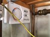
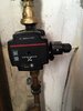
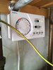
Neither CH or HW are working. I'd only been using HW during summer and when it stopped working I suspected a faulty pump as it had been noisy before stopping. I changed the pump, no change. Neither boiler on or lockout LED were lit on front of boiler control panel.
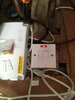
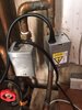
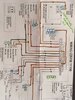
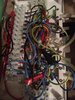
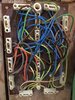
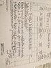
Called engineer who charged £140 - he took front fire off and set the CH room thermostat to call for heat, the pump started working but boiler didn't fire up, HW on alone didn't start the pump. I noticed an orange LED on the PCB was lit - I now know there are 3 LEDs there, one Live, one switched live and one ignition. He said it was a power issue from the controls so i'm guessing it was permanent live lit. He said the HW motorised valve was faulty and quoted £820 to replace it and said a further £180 may be needed to rewire the control box. I replaced the HW MV - no change. I bought new wiring box box and rewired it, possibly slightly differently to old one. Now turning HW on makes the pump start but no boiler fires, CH on doesn't start the pump [so a reverse of what was happening previously]. Fire front was replaced so I can't check which LED on the PCB was lit. I don't want to replace boiler and change all pipework. If I have a better idea of what might be wrong I'll know if any quote seems reasonable. The £140 was meant to include an attempt to fix plus cost of any parts, there was no attempt to fix so I felt ripped off for a 10 minute inspection and am now looking for a different engineer. Any help would be appreciated, I'm not really confident to be testing terminals with a multimeter even though I know there are videos showing how to do this. I followed the diagrams for the wiring of an S plan so hope I got it right. Cheers
 
Sponsored Links
You have been completely ripped off, dont use this clown again, where in the country are you , possible a decent lad from here can help you out, great boilers and simple to those who know how they work, post some pics of controls motorised valves thermostats , anything that you have
 
Hi Ian

I'm outer london/Kent borders.

The boiler is downstairs and controls in bedroom above next to HW cylinder. The spur socket is lit. The lights come on for both HW and CH at the timer, the LEDs light on the pump (previously CH only - but now since the rewire - HW only). It can't be the motorised valves as the CH (left) was working and the replacement HW valve lever (right) moves when turned on. As the old wiring box had never been touched I think its unlikley I've created an almost identical fault in the new one. I'm thinking I might try swapping out the timer because if it isn't that I think it must surely need somebody who can properly test the electrics in the boiler.

I know I was ripped off because the engineer said my air vent was insufficient, but he didn't take account of the room being open plan to the kitchen and the 2 additional air vents there. After confirming this was a requirement for the boiler only I wanted to double check it was still safe to use my gas fire - he said you won't be able to as I've turned the gas off to the fire. Gas safe have confirmed this should not have been done without my consent unless it was thought dangerous, he wouldn't have even mentioned it if I hadn't commented. I think he was trying to force me to have him back but as I have an immersion heater and I've bought some electric panel heaters to keep warm now the fire can't be turned on I definitely won't be. I'm counting my lucky stars that I didn't pay him to do the HW motorised valve. I should be fair and say the quote was for both M. valves and he said the current pump valves are "not the best" so that was included even though both are operational, he also said a service would have be included in that price, it was rolled up as a total price so I don't know what the breakdown would be. He left his reading glasses at his previous job so spent much of the short time ringing his office to arrange to collect them after finishing at mine. I was working from home downstairs so didn't see what he tested upstairs. After I googled the motorised valve I checked it would move manually, which it did, so I tried changing only the head which didn't help, then changed the whole thing, which again didn't help.

I'd really like an idea of what might be wrong before spending any more money paying somebody to guess what the problem might be.

Hoping somebody may have some ideas
 

Attachments

  • thumbnail_IMG_3468.jpg
    thumbnail_IMG_3468.jpg
    67.7 KB · Views: 83
  • thumbnail_IMG_3469.jpg
    thumbnail_IMG_3469.jpg
    43.5 KB · Views: 96
  • thumbnail_IMG_3470.jpg
    thumbnail_IMG_3470.jpg
    67.3 KB · Views: 114
  • thumbnail_IMG_3471.jpg
    thumbnail_IMG_3471.jpg
    92.5 KB · Views: 98
  • thumbnail_IMG_3472.jpg
    thumbnail_IMG_3472.jpg
    43.9 KB · Views: 107
  • thumbnail_IMG_3473.jpg
    thumbnail_IMG_3473.jpg
    45.1 KB · Views: 81
Would love to know what motorised valves he was going to fit that are better than Honeywell, he is talking absolute drivel, if you have a multimeter, remove the cover on the wiring centre and switch CH and HW both to on and test for 240V AC between the orange wires and Neutral , be carefull lots of live wires in there
 
Sponsored Links
Yes he does need your consent to turn the gas off, I’d be questioning this with the company. Did he leave you a warning notice for it? Is this because of the “insufficient vent”?
 
Hi Ian I’ve uploaded the pics of the old wiring, brown board on back, and the new wiring and the diagram that I used, I’ve written over it, but you can see that I’ve got both orange wires sharing the same slot, when you say test with neutral do you mean any of the neutral wires? Will a multimeter help when both are slotted together? I may need to take some brave pills before considering the multimeter as I’m sure some wires are switched lives that haven’t had brown sleeves added, I’ve stuck bits of red electrical tape over those but I can’t be 100% sure this thing is wired properly. It’s very odd that despite wiring the box from scratch it has an almost identical fault to before. Gas is on to the boiler, it was only turned off to the fire front with no labels and like I say he wouldn’t have said anything if I hadn’t wanted to double check the fire was okay to use
 

Attachments

  • 4C875DD5-5623-48CD-A8BA-14D40400DA2C.jpeg
    4C875DD5-5623-48CD-A8BA-14D40400DA2C.jpeg
    73.5 KB · Views: 164
  • CCACBD3B-3013-4043-A655-1E3313B3087E.jpeg
    CCACBD3B-3013-4043-A655-1E3313B3087E.jpeg
    64.4 KB · Views: 113
  • 509D8D85-8DD6-4580-A3E1-DE60B85488FB.jpeg
    509D8D85-8DD6-4580-A3E1-DE60B85488FB.jpeg
    75.7 KB · Views: 95
yes the orange wires should both be in the same terminal, that is the switched lived from the zone valves asking the boiler and pump to come on, if you have 240 there then external controls are all OK and the fault is at the boiler end, if you dont get 240v then it is an external control issue
 
I'm not really confident to be testing terminals with a multimeter even though I know there are videos showing how to do this

That is why the engineer will charge, but the guy you called must be thinking you are made of money or a fool who will easily part with £800 odd. Such person deserves to tarred and chased out of town.

Fault finding on that unit is a walk in the park.
 
It’s a shame I don’t know more about the initial diagnosis, attached. The leaking drain valve is a red herring as I explained it had a tub under it to catch any drips as I hadn’t tightened it as fully as I could after fitting the pump. It was the pump valves he said weren’t the best, the lower one did isolate but I replaced the upper one with what I thought was like for like as that seemed seized, the lower screw isolates by a small turn, the upper screw does seem to keep turning without meeting any resistance, anyhow water goes through the pump so I don’t think that is the issue, I left the screw vertical as I presume that’s open.
I’ve been brave and had the multimeter out. Hw on 240v between orange and neutral and pump only starts not boiler. ch turned on alone at programmer and thermostat calling for heat 0v and no pump start and both on 240v. Does this help to narrow it down? Obviously I may have introduced a fresh fault by rewiring the box but essentially nothing has changed.
 

Attachments

  • 2A587AC2-15E6-4B53-90D4-F90643F059F3.jpeg
    2A587AC2-15E6-4B53-90D4-F90643F059F3.jpeg
    66.2 KB · Views: 73
  • 7B345C8B-9453-4C57-8229-B78941CDE45F.jpeg
    7B345C8B-9453-4C57-8229-B78941CDE45F.jpeg
    70.3 KB · Views: 85
The first problem to solve is why is the boiler not firing?
The second problem is either failed microswitch or wiring issue but trying to solve both at once can get confusing.
When HW is set to call for heat, are terminals 12 and 13 in your wiring centre at 240v?
 
This might be the time to add that when I re-wired the box there were 2 cables which disappeared under the floorboards that I couldn’t trace, one to the boiler and one to the room thermostat. The boiler cable seemed thinner where I could see it in the room below so at the box I treated the fatter cable as the room stat and thinner one as the boiler, there’s a possibility I’ve got these the wrong way round
 
To test the voltage at terminals 12 and 13 do I connect the multimeter between each one and a neutral, same procedure as testing the orange wires? Thanks
 
Yep, that's the one. And that's not ideal (your guess the cable trick)- especially with the thermostat there is no guarantee that the cables are terminated in any sensible fashion (colour wise). You need to ID those cables for definite (and ensure that 240v and neutral and earth are definitely getting to the boiler- safest way to ID cables is isolate all supplies, mark and disconnect at the wiring centre what you think are the cores to the boiler, go to boiler, check resistance between live and earth (should be high or infinite). If true, go back to wiring centre, connect live and earth of boiler cores, retest at boiler for resistance (should be very low or zero). Repeat process with live to neutral to verify all 3 cores.
 
I took up floorboards and boiler cable is the one I thought it was. With no call for hw 12 is 240v and 13 is zero, when hw called both are 240v. I really appreciate the help on this as I only just grasped the wiring without any testing. One video I saw said for a 2 port system it is the grey wires and not the browns from the motorised valve that are the permanent lives, my wiring diagram labels brown as live so that’s what I followed.

As 12 and 13 both have 240v when hw is called does that mean the main reason fault is likely to be in the boiler?

Does the CH not doing anything mean there is also likely to be a control or wiring issue affecting that?

Thanks for the help so far
 

DIYnot Local

Staff member

If you need to find a tradesperson to get your job done, please try our local search below, or if you are doing it yourself you can find suppliers local to you.

Select the supplier or trade you require, enter your location to begin your search.


Are you a trade or supplier? You can create your listing free at DIYnot Local

 
Sponsored Links
Back
Top