M
mysteryman
It looks as if it is installed correctly as contraflow to me.

Perhaps he recognised the advantages - such as decoupling the conflicting requirements of minimum flow through boiler vs variable flow through CH system with all TRVs and modulating pump ? I'm not surprised to see plumbers spouting unnecessary venom when a TS or HB is mentioned.I may be missing the point but what was this all in aid of?
Why not just a boiler and unvented hot water cylinder.
Chuck the heat bank.
Simples.
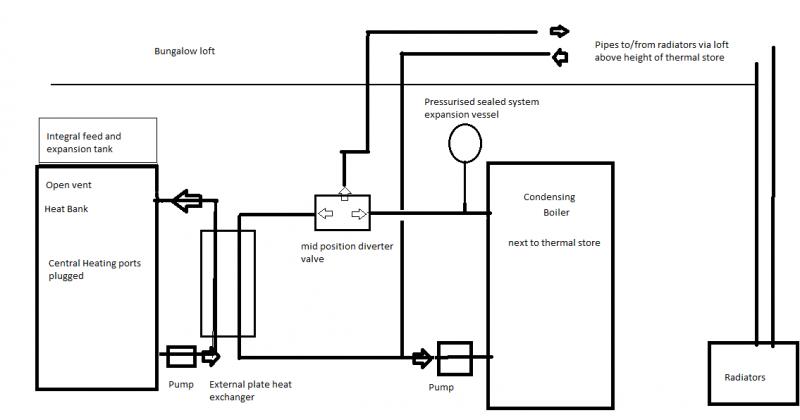
But back to the original query, I can't see what the problem is - what does the location/route of the radiator plumbing have to do with the boiler circuit ? I'm assuming there is a F&E tank somewhere (hopefully at the highest point of the system) - as long as this is high enough to give sufficient head for the boiler and not too high for the store and boiler pressure rating, then the CH connections are irrelevant to the boiler. All the boiler "sees" is the head from a F&E tank providing a head to a direct cylinder.
As I understand it, the boiler circuit has to be part of the CH. I don't want a FE tank or anything in the loft, so I intend to have a sealed CH system which requires an expansion vessel.
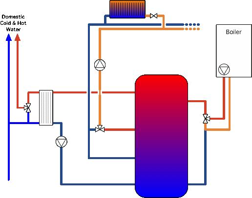
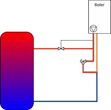
The return to the boiler can come from the bottom of the store (you'll want to move it up when you get the solar installed), the flow from the boiler goes into the top of the store.
Yes there are dedicated ports for these on the HB.
You'll need to modulate the flow rate, or the return temperature, so that the flow temperature is hot enough to heat the bank top-down
Ok, now you're talking.
- although your heat exchanger setup is poorly designed in that respect and will very quickly de-stratify your store.
I assume you are referring to my diagram and not confusing the DHW side in the photo?
For my store, I used a TMV in the return line, mixing hot water from the boiler flow with cold from the store bottom
I have a TMV for this purpose but the company who I bought it from don't have a diagram, can you refer me to a diagram somewhere?
- in my case I still have a non-condensing boiler and so wanted to avoid condensing.From an efficiency POV, you would want to keep the return to a condensing boiler as cool as possible and vary the flow rate to get the flow temperature you want - but obviously there are limits imposed by the design of the boiler.
Yes this is one of my concerns and is this achievable when the boiler flow and return are just circulating through a PHE when only the HB needs charging?
Stratification is important - and also (in part) why I decided on a thermal store rather than heat bank for my flat. To get optimal results, you need (as someone pointed out) contra flows in the heat exchanger AND to match primary flow rate with DHW flow rate. If you can match the flow rates properly, you'll then be able to return cold water to the bottom of the store that is only a few degrees warmer than the incoming mains.
Hang on, you are talking about the DHW side now, although I presume the same principle applies.
The colder you can keep the bottom of the store, the more effect you'll get from your solar when the weather is marginal.
However, as you have it, your return will never be cooler than your DHW flow AND your primary flow rate will need to be at least as much as needed to satisfy your highest DHW flow rate - under any other conditions it will be higher than needed and primary return to the store will be hotter than necessary.
Well I remember reading somewhere a suggestion for using a TMV to somehow control the temperature of the return to the bottom of the HB from the DHW but again no diagram.
.I would suggest you may find the folks over at the Navitron forum more welcoming - there are a few people here who cannot (or will not) accept that anything other than a combi boiler (or at a pinch an OV DHW cylinder) has any place for anyone or anywhere
Ok I will try my luck with them. Thanks for your help.
I wrote up my install in this thread and there's a schematic near the bottom of the first page. Apart from you having an external DHW heat exchanger instead of an internal coil I see no reason you can't do just the same.
I read your interesting article. I will need to study your sketch with fresh eyes next week.
I'd suggest going back to the boiler manufacturers and asking their recommendations for "heating an open vented thermal store - how would they recommend controlling the boiler loop flow temperature to ensure top down recovery ?"
Already asked them. They were helpful but said they don't provide system diagrams.
Also, just looked up, I started a thread here where the subject of store stratification when using an external heat exchanger was discussed. You may find it interesting - or a laugh
Read that too. V interesting but a bit over my head I'm afraid.
I'll get back to this next week. Thanks again.
OK, you'll already have a F&E tank somewhere - although looking again I see you've got one integrated into the top of the store. Where is this in relation to the rest of the CH ?As I understand it, the boiler circuit has to be part of the CH. I don't want a FE tank or anything in the loft, so I intend to have a sealed CH system which requires an expansion vessel.But back to the original query, I can't see what the problem is - what does the location/route of the radiator plumbing have to do with the boiler circuit ? I'm assuming there is a F&E tank somewhere (hopefully at the highest point of the system) - as long as this is high enough to give sufficient head for the boiler and not too high for the store and boiler pressure rating, then the CH connections are irrelevant to the boiler. All the boiler "sees" is the head from a F&E tank providing a head to a direct cylinder.
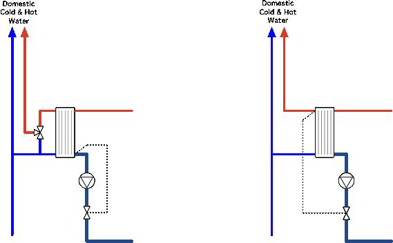
I was talking about the DHW side - someone else picked this up, I didn't notice it, but it looks like both the primary and DHW flows are downwards in the PHE. Ideally they should be opposite - probably make the DHW flow upwards and the primary flow downwards. Doen that way, and with the flows accurately matched to load, the return temp into the bottom of the store would be quite close to the incoming cold water supply temp.I assume you are referring to my diagram and not confusing the DHW side in the photo?- although your heat exchanger setup is poorly designed in that respect and will very quickly de-stratify your store.
See the diagram I linked to. it's the three port valve linking boiler flow and return, and the store.I have a TMV for this purpose but the company who I bought it from don't have a diagram, can you refer me to a diagram somewhere?For my store, I used a TMV in the return line, mixing hot water from the boiler flow with cold from the store bottom
- probably make the DHW flow upwards and the primary flow downwards. Doen that way, and with the flows accurately matched to load, the return temp into the bottom of the store would be quite close to the incoming cold water supply temp.
Your diagram for the boiler loop does have the flows correct.
OK, I can see there being problems getting the rads filled initially, but I can't really see why a loop of pipe going higher than the F&E tank should stop the system working. The pipes are sealed so will not admit air (if they did, then they'd have let water out normally) - they'll just be at a bit less head - about 25' absolute instead of 30' absolute.No I had'nt missed this. I wanted/expected to be able to connect the flow/rtn pipes to/from the rads to the dedicated ports on the store. But then I realised (after connecting it up) that those connections are Direct (no internal coil) and the pipes to/from the rads rise above the height of the store which is Vented and I presumed that this will not work because water finds its own level plus the effect of the CH pump etc I envisaged water bubbling out of the integral FE tank overflow and/or interfering with the other Direct ports.But the key thing you seem to have missed is that the CH does NOT have to come direct off the boiler - and there are some significant benefits by running it from the store instead (more if you had a condensing boiler).
The only difference really is that you won't be able to use air vents (manual or automatic) in the loops to let the air out.
I would give serious consideration to buying a standard F&E tank and putting it in the loft. It will be a LOT cheaper, and a LOT simpler than the messing around you are planning with PHEs and so on.
No, because they would be above the water level in the integral F&E tank. So rather than letting air out, they'd let air in.Is this because it would be a sealed system?The only difference really is that you won't be able to use air vents (manual or automatic) in the loops to let the air out.
You'd just disconnect the integral F&E tank and take the pipes up to the one in the loft. This only needs to be just higher than the pipes for air vents to work - there's an argument that manual vents might be better, automatic ones tend to stick and either leak (fail to close after venting) or not vent (fail to open) when they've been in and inactive for some time.So if I put a F&E tank in the loft, it would not be a sealed system and then I would be able use auto air vents? And I would just use the integral F&E on top of the store to initially fill the store, or should I just fill the whole system from the F&E tank in the loft?I would give serious consideration to buying a standard F&E tank and putting it in the loft. It will be a LOT cheaper, and a LOT simpler than the messing around you are planning with PHEs and so on.
.As I see it, a F&E tank will set you back some modest amount (£20-£30 complete with fittings ?). To connect your boiler and CH loops up, you'll just need a TMV for the boiler loop (I'm assuming you already have the pump), and a pump and TMV for the CH loop (though I'll admit a Grundfos AlphaII modulating pumps isn't cheap at around £100).
It depends on what you are going to do. I chose it because it will regulate the flow right down to zero - and it backs off both the power it used, and the pressure in response. What this means is that you can fit TRVs to every radiator without a bypass and without the system getting noisy. If you try that with a fixed speed pump, then at low flow rates the pressure rises and the valves get noisy..As I see it, a F&E tank will set you back some modest amount (£20-£30 complete with fittings ?). To connect your boiler and CH loops up, you'll just need a TMV for the boiler loop (I'm assuming you already have the pump), and a pump and TMV for the CH loop (though I'll admit a Grundfos AlphaII modulating pumps isn't cheap at around £100).
I already have a spare TMV and a Wiflow pump. I presume the Grundfos somehow regulates flow, is it really important?
It looks like both the primary and DHW flows are downwards. You want one up and one down. Partly because that's the logical way to do it, the DPS heatbanks pump the primary flow downwards, and then that sets the DHW flow rate as being upwards. It doesn't matter which goes up and whch goes down as long as they go opposite directions.Did you see my reply about the DHW flow? I might be attacking it this weekend so be nice to get it right as I have already changed the arrangement once.
I have no qualifications specific to plumbing or heating systems, but I do in other areas. I do have a certain amount of DIY experience with plumbing/heating.Do you mind me asking, are you some kind of an engineer?
That would be a good idea. Drawing a diagram will also help you get your ideas together - more than once I've had a great idea and then I drew it out and found that perhaps it wasn't so good after allI am going to make a diagram based on your very helpful info and put a diagram together and see if you agree

If you need to find a tradesperson to get your job done, please try our local search below, or if you are doing it yourself you can find suppliers local to you.
Select the supplier or trade you require, enter your location to begin your search.
Are you a trade or supplier? You can create your listing free at DIYnot Local
