Pictures of wired CU's

Joined
19 Jan 2007
Messages
4,287
Reaction score
394
Location
London
Country
United Kingdom
A while back there was a post (that I can't find) showing various CU's with all wiring in place.

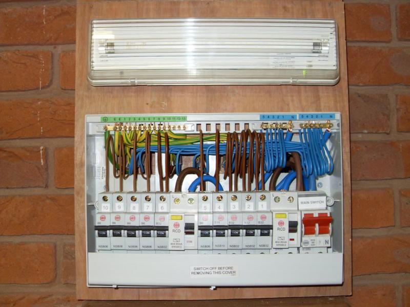
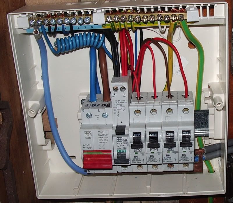
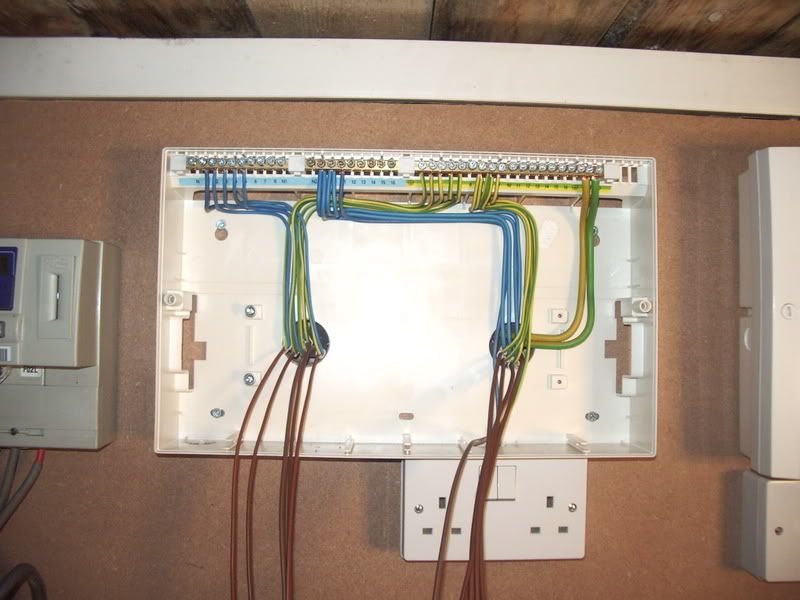
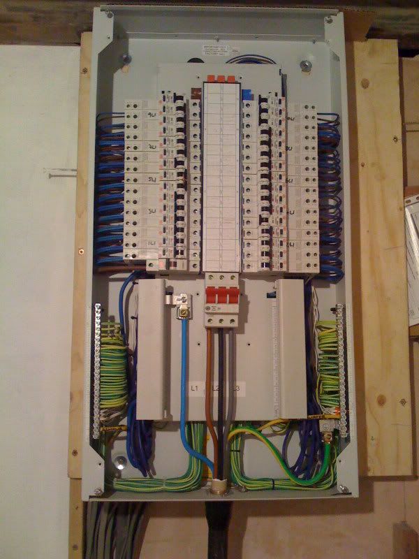
There were a few that had been done very (very) well as in the layout of the LNE's looked really nice, well formed and sexy (in a sparks sort of way :LOL: ).

I've had a hunt about with the search facility and can't find them.

Could someone post links for the old post, or alternatively if you've done some recently please post a picture.

I'm changing my CU on Friday and would just like to take on some tidier methods.

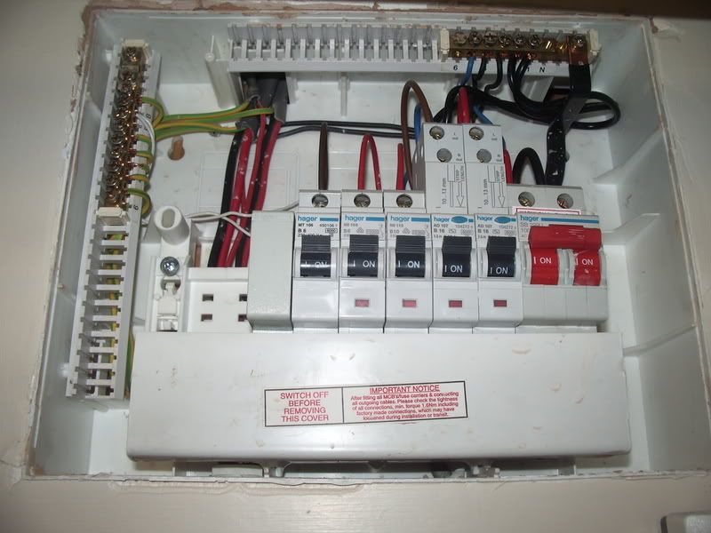
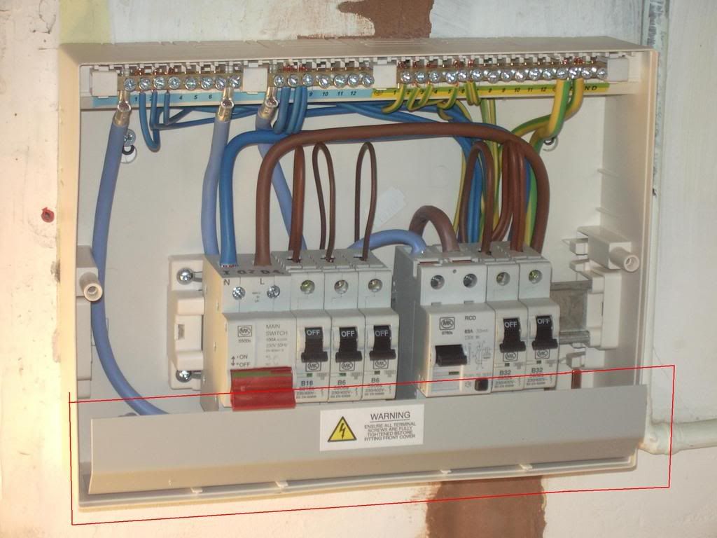
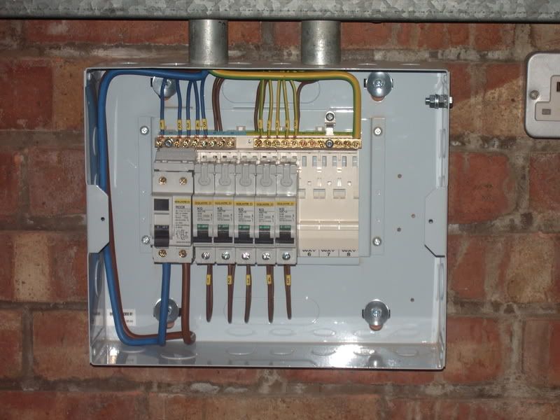
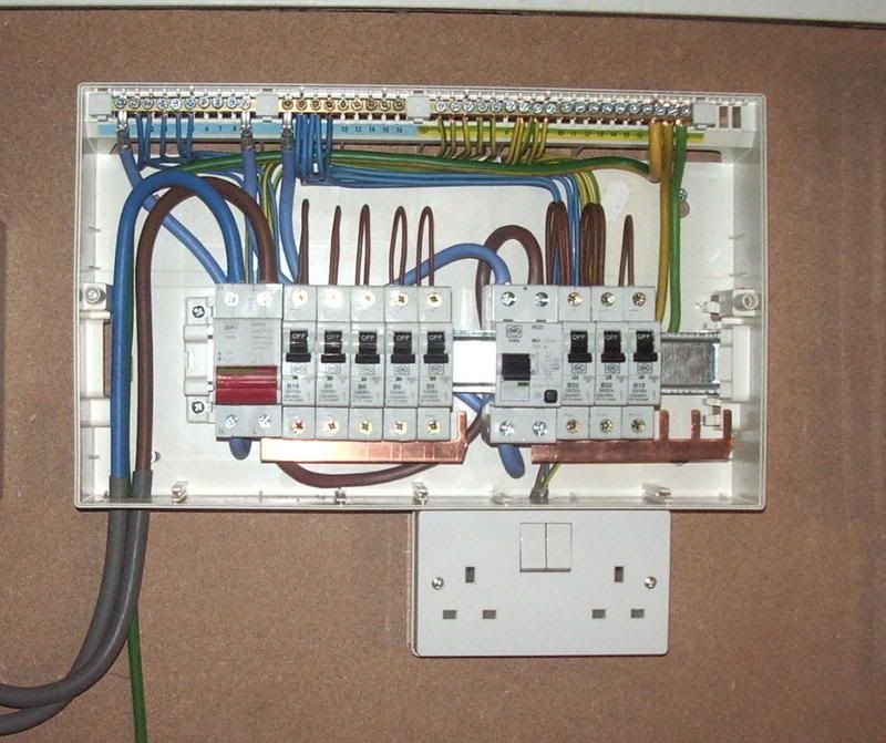
Here's one I did earlier, which I know has room for improvement.


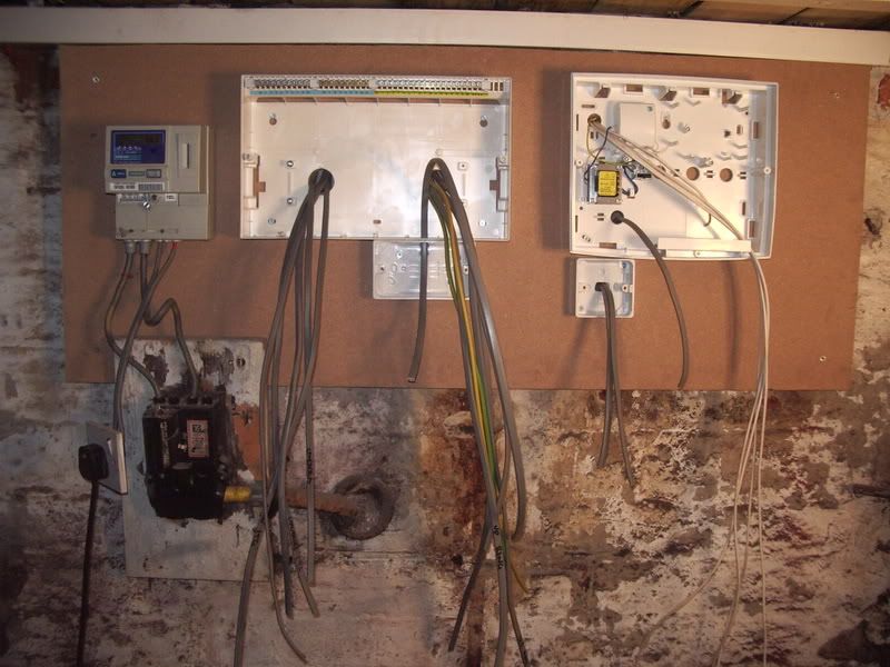
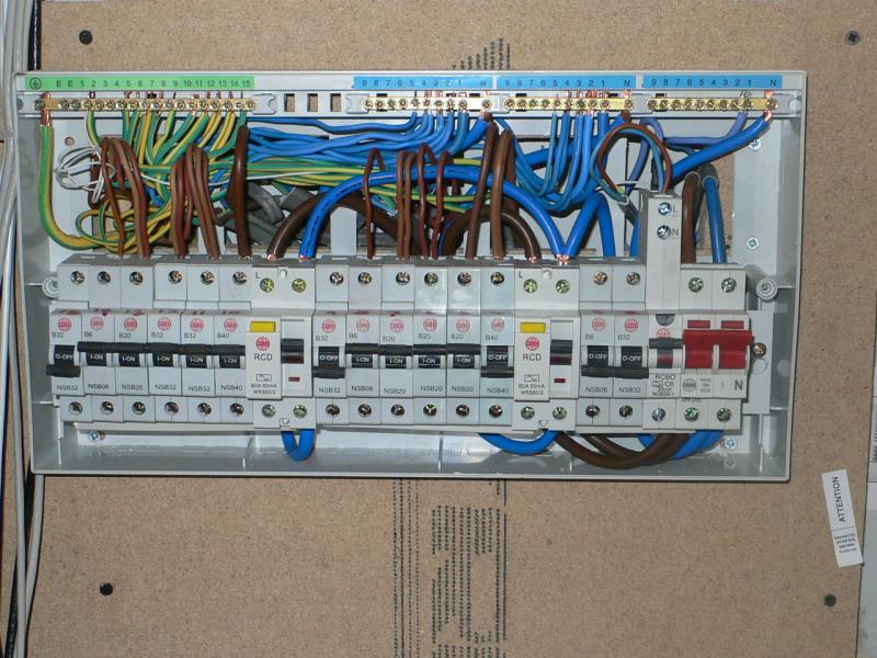
The new board for home has a cavity behind it and the board will be part set in to the wall, this will give me some room to loom the cables to the correct CU position avoiding the sort of mess you see in the picture posted.

Out of interest, since the cavity is behind the board and totally enclosed can I have cables stripped of overall (not core) sheath in the cavity ?
 
Sponsored Links
I can't answer any of your questions I'm afraid but I'd just like to comment that in my panel-wiring days, which involved mostly MCBs and RCDs, neatness was paramount. Cable routes, angles of bends and amounts of spare required to be left for remakes were often specified, and ALL cables had to be terminated with an insulated crimped lug or ferrule. Any exposed copper at a termination was a serious offence!

There is usually more room in a panel than a CU however.

The CU wiring in the picture looks fine to me but think how it would look with crimps on all the terminals, in lovely red, yellow or blue! You never see these in CUs. Are they allowed?
 
Are those links factory fitted chri5? They are a bit messy and poorly terminated.
I would not strip the outer sheath off cables in a cavity as it is not an electrical enclosure !
 
Considering that this is a "busy" CU you will find that it is quiet hard to get the wires as you wish. I think that the installer made the effort to do the installation nice and nit. Looking at the cover on photo, you can see that there are the required stickers and the purpose of the CBs is marked.

How can it be improved, IMHO;
- You can add numbers on the CBs.
- You can add numbers to the wires (that will be the same as the relevant CB number).
- Mark the 2 legs of the ring circuits, i.e; circuit 3 of the middle RCD look like ring circuits, I would mark one leg (L,N and E) with the number 3 and the other leg 3A or 33. This will not make any difference to you as a user but in the long term when the installation has to be inspected it might make a big difference.
 
Sponsored Links
personally the only things i would do that as fas as i can see you haven't is to use terminal1 on neutral / earth bars for Mcb 1. Term 2 for Mcb2 etc
and then number insequence if i had to double up on the bars because of shortage of terminals then i would number the cables as suggested in a previous post but i still wouldn't mix cable sizes.
thats not to say there is anything wrong with your example just i'm pedantic about the way i do it :LOL: :LOL:
 
I'm Click-sure hunting :D

Found it :D


So back to the 'cavity'- on Clicksures pretty installation all the cables seem to be stripped back behind the CU in his man made cavity behind the CU.

If your saying that a solid brick and rendered cavity behind my CU doesn't count as an electrical enclosure, then how would clicksures ?

I want to do a picture by picture installation for a web site I intend to build on my own instal, so I'd like to be clear on the method used.

Is it acceptable to have the cable stripped behind the CU in a brick and render cavity, it does have a firestop (firequell) where the cables access the cavity.

Thanks for any words of wisdom, even BAS :D
 
personally the only things i would do that as fas as i can see you haven't is to use terminal1 on neutral / earth bars for Mcb 1. Term 2 for Mcb2 etc and then number in sequence...

I agree this is a part to mention because I thought that it is obvious, CB, terminal and wire numbers for a certain circuit are the same. This is a great help in a CU when you need to identify which N belongs to which L and the same for E.
 
The factory flex links can be bent into little "U"'s as they enter the RCD's and tucked behind the circuit breakers.

I like to loop the phase conducters behind the circuit breaker DIN rail too, so they pop out from behind their respective MCB and loop in.
 
Here is one or two I have done (some 16th, some 17th)

IMGP19112.jpg


IMGP3085.jpg


sheild.jpg


kitchenfusebox.jpg


IMGP1750.jpg


Step by step guide:

IMGP1330.jpg


IMGP1336.jpg


IMGP1343.jpg


Chrissboard.jpg


IMGP1353.jpg


2nd pic down, is that a garage submain? - the supply cables look a bit teeny.
4th one down, looks luvly! Did you get a cup of tea whilst you were there?
 
2nd one down is the submain in my shed, It's fed in 6.0mm², and only a short run from the garage anyway.

4th one down, I turned down the tea
puke1.gif
 
Oh, couple more 17th edition boards from my phone

Iphone063.jpg


Iphone171.jpg

This really was in a domestic property :eek:
 
How do you find those Wylex 3PH boards Rob?

I find the breakers have a tendancy to like to sit at a bit of an angle making it a bit of a game getting the board cover on :LOL:

That board was a little while ago as well? those look like the older style PSB breakers?
 

DIYnot Local

Staff member

If you need to find a tradesperson to get your job done, please try our local search below, or if you are doing it yourself you can find suppliers local to you.

Select the supplier or trade you require, enter your location to begin your search.


Are you a trade or supplier? You can create your listing free at DIYnot Local

 
Sponsored Links
Back
Top