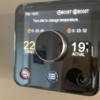
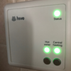
Potterton EP2002 to Hive Active heating and hot water help!

Joined
5 Dec 2017
Messages
8
Reaction score
0
Country
United Kingdom
Hi there, a first time user on here and having seen the amazing help provided I thought I would ask for a little myself on the install of the hive system from a potterton EP 2002.

I genuinely thought this to be a fairly straight forward job until I noticed (as others have) the amount of wires behind the programmer but having read some interesting threads on here it would seem that for the hive not all are required therefore pushing me to giving it a go!

I have provided a couple of pics, the main one of interest is the programmer back plate.

Thanks in advance, any help would be really appreciated! Oh and i have called a few plumbers today but not looking good so I'm hoping to have a crack at it! :)

Pls could someone advise also how I put images on here, sorry.........
Pic 1 is the Potterton EP2002
Pic 2 is the Vaillant eco max pro boiler

cheers, Stu
upload_2017-12-5_12-22-26.png


upload_2017-12-5_12-23-45.png
 
Sponsored Links
Hi Stu and welcome to the forum.

The EP2002 is a bit unusual because it is a Programmer and Wiring Centre combined. The terminals A B C & D are just terminals provided for convenient use by the installer. They are simply used to connect wires together and are not connected to the programmer functions. Your biggest problem is that the Hive does not have this 'junction box' facility to accommodate so many wires. To get around this, I would normally sink a single gang flush mounting socket box in the wall behind the programmer to house some additional new terminals used to replace them. In your photo such a box appears to be existing already (lucky you :)). As it's metal socket box, make sure that it has an earth connection.

This extra wiring whilst not "rocket science" does mean that you need to be competent with electrical installation procedures to do this safely. If you feel unsure, please get someone professional to do it.

If you are competent to proceed, you will need 4 new extra terminals to replace A, B, C & D. All of the wires presently contained in 'A' go into one of them, all of the wires from 'B' go into the second, 'C' the third, and 'D' the fourth one. Make sure all of the connections are good, and that there is no copper exposed from the terminals that could inadvertently come into contact with the metal back box.

N and L are straightforward they are the same for the Potterton and the Hive, so they simply transfer.

Earths from the EP2002 go to the Hive's earth tether. As there are a lot, you may have to put them into a separate terminal first if required, but they all do need connecting together.

Then it is a matter of moving the remaining wires from the main switching terminals as defined on the back of your EP2002 (1, 3 & 4) as below

EP2002.JPG

to the corresponding terminals at the Hive. Which is straightforward in this instance. [for example 'HW On' (EP2002) corresponds to 'Hot Water On' (Hive)] Even the numbers match up in this case. (lucky you again!:))

The link between L and 5 on the EP2002 does not need to be retained, this connection is made internally by the Hive.

Hive.JPG

Electrically speaking, as the Hive Dual Channel Version, has the same switching functions as the EP2002, then the operation of the Hive will replicate what the EP2002 does for you now and the way that it interfaces with the existing Vaillant controls.

The only other issue would be if you have an existing room thermostat somewhere. Because the Hive carries out the functions of the room thermostat as well as the EP2002 programmer, the old wired thermostat needs to be decommissioned to prevent it overriding the Hive. It can't simply be disconnected as this would leave the heating wiring 'open circuit' and it will not operate. The thermostat can be decommissioned in three ways, in order of preference, they are.

1. Find the origin of the thermostat cable and disconnect it. Then link the terminals where the two switching wires came from together.

2. Remove the existing thermostat and replace it with a junction box, connect the two switching wires together and isolate the neutral (if there is one)

3. Leave the existing room thermostat in place and put both of the switching wires in 'L' terminal (or set it to the highest setting and hope that no one moves it)

If you need any further assistance with this, post back details of your existing thermostat make / model and what wires are connected to which terminals.
 
Wow, you are goooooood Stem. Thank you kindly that has given me something to get on with! I'll report back once I have got started as off to sort kids out now.

Thanks again !! :mrgreen:
 
Hi Stem, apologies but a quick question as I'm having a look now (promise not to ask many), the blue wire in terminal D is alone and since the terminals A,B,C and D are used to connect the wires is this correct as its on its own?

Thanks
 
Sponsored Links
Nearly there, I note you mention the link between L & 5 does not need to be retained but there is another red wire in 5 as well as the link between L & 5, where should I place this one? sorry.....
 
That needs to be connected to the L. If you follow it back you can see that's where it is connected now via the link
 
Up and running with hot water and heating thank you for all your help!! I've never been on threads etc like this but my god have you helped me! Without sounding too cheesy I will chuck a couple of pics on after work once I've attempted the thermostat which hopefully is a walk in the old forest compared to what I just went through!! o_O:LOL:

Only thing I am concerned about is the chock blocks I used to replace the job of terminals A-D but they are solid and tight connections as long as they can withstand any heat passing through them if any?! A good friend who couldnt help today has also advised that should anything go wrong the 3amp fuse will blow in the mains socket before anything else has a chance to pop!

Thanks again :D
 
Only thing I am concerned about is the chock blocks I used to replace the job of terminals A-D but they are solid and tight connections as long as they can withstand any heat passing through them if any?!
The currents flowing through the connections are tiny, there won't be any heat generated, worry not.

A good friend who couldnt help today has also advised that should anything go wrong the 3amp fuse will blow in the mains socket before anything else has a chance to pop!
Quite right that's why it's there.

Thanks for the update and well done, you need a fair ability of your own to work out first of all my waffle and then follow it through. It was nice to give advice and know that you had understood what you were doing.

Edit
Ps, sorry I missed this from earlier.
Hi Stem, apologies but a quick question as I'm having a look now (promise not to ask many), the blue wire in terminal D is alone and since the terminals A,B,C and D are used to connect the wires is this correct as its on its own?
The answer is yes. It keeps it out of harms way.
 
Last edited:
Haha yes all waffle greatfilly received! All is working fine but I need to manually switch on heating/hot water at the moment as not done thermostat due to work/kids/life etc!! I’m going to get it done today as from what you have said it seems to be the easy part and at very worst I can leave there on full and hive will override but to be honest I think if at all poss I’m going to choose option 2 and hopefully find two wires once Honeywell stat removed and simply connect them with a block to make circuit with the theory that the hive will then take over and speak directly to the receiver. (He says).

Will update this afternoon as to the success of the operation and hopefully ‘control my heating from my phone’ :whistle:
 
upload_2017-12-7_13-32-55.png


Ok, so one last painful question (sorry). If I am to remove the stat and leave cable this end blocked, which are the two switching wires as theres 3? Then I would block off the earth and tape up before poking back into wall.
 
Here are a few options for you.

Stat Model (1).jpg

I haven't shown the earth, but it can remain where it is in option 1, and be inserted into a spare terminal in the junction box in option 2. Option 3 however would be the best method. Here the cable is dead, so you can do what you like with it.

The only option that will allow you to push the wires back in the wall is option 3 as they won't be live anymore. With options 1 & 2 the wires are still live and so must be contained inside an accessible enclosure.
 
Thank you mate!! All sorted now couldn't have done it without you're help (obviously) but **** I surprised myself....

Some pics below are of the old Honeywell thermostat before it was made safe, I connected the two live red wires (1 switch) then blocked off the neutral and the earth with chock blocks followed by insulating tape and replaced the old case so hopefully this will be enough.


upload_2017-12-7_18-38-16.png upload_2017-12-7_18-38-51.png upload_2017-12-7_18-41-14.png


All good and working as far as I can tell so cheers dude, really appreciate all your help!!!

Stu
 
Just wondering. I have the same system and have followed the instructions here but I thought you could have the hot water on but the heating off, but mine seems to run both at the same time.
I’ve wired the receiver as shown (removed the live link) and shorted the red and yellow at the thermostat.
Can’t figure out how to turn the heating off and run just the water. Both lights on the receiver are on whenever the heating or hot water are on.
 
There are two common types of heating system where stored hot water supplies are involved.

1) Fully pumped with motorised valve(s) that allows independent control of the central heating and hot water.

2) Pumped central heating with gravity circulation of hot water, where the hot water must be 'on' before the heating can be 'on'.

Hive can cater for both types but must be set up accordingly. For separate control of the heating and hot water, the Hive should be set to fully pumped mode, which is the factory set mode. It sounds like yours may be set to 'Gravity fed and part pumped mode' which will not allow the heating to be on without the hot water. Page 13 of the Hive manual explains how to change it, under "Important Information - Gravity fed and part pumped mode".

The odd bit, if this is correct, is that you say that you can't have only the hot water 'on' on it's own.

Your plumbing will of course need to support the fully pumped mode of operation. But if you had independent control previously it should still function with the Hive in the same manner as before.
 
Last edited:

DIYnot Local

Staff member

If you need to find a tradesperson to get your job done, please try our local search below, or if you are doing it yourself you can find suppliers local to you.

Select the supplier or trade you require, enter your location to begin your search.


Are you a trade or supplier? You can create your listing free at DIYnot Local

 
Sponsored Links
Back
Top