Pyronix Enforcer - bell not sounding during Test Siren?

Joined
28 Feb 2017
Messages
69
Reaction score
0
Country
United Kingdom
Hi,

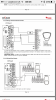
I have the latest Pyronix Enforcer Homecontrol+ App v2.1 panel, and just received the Deltabell Plus sounder. I have wired it up but it needs confirming if correct, but both the backlight and strobe lights flash, but when doing a siren test under Engineer Tests menu, the strobe and backlight flashes but no sound from the siren. Is it supposed to sound? Below is the wiring between the panel and sounder:

Backlight Disable
T >>>> -D1 (RS485 -0v)
T >>>> Z33 (Input 33)
Eng. Hold >>>> PGM (programmed as Option 59 Engineer Access)
Bell >>>> Bell
Str >>>> Str
0v >>>> Com
12v >>>> 12v

Is this correct?

If I also want to disable the backlight, does this connect to 0v also?

Does a 2K2 resistor need to be connected between the two tampers?

Thanks
 
Sponsored Links
I have made some progress and the alarm now sounds under the Test Siren option. All I changed was adding a 2K2 resistor from one of the tamper connections on the bell to panel's -0v. The wiring is now like this:

Backlight Disable >>>> not used
T >>>> D1- (RS485 -0v) with 2K2 resistor in series
T >>>> Z33 (Input 33)
Eng. Hold >>>> PGM (programmed as Option 59 Engineer Access)
Bell >>>> Bell
Str >>>> Str
0v >>>> Com
12v >>>> 12v

However, the tamper lid doesn't seem to work now despite coming out of engineer mode. Also tried connecting the uppermost T connection on the bell to 0v. Any ideas anyone, please?
 
check bell lid tamper, theres a microswitch on an adjustable panel with a screw. Turn the screw towards the wall & the switch will move out towards the lid. When you close the lid listen carefully for a click from the switch. If its not that you have a wiring issue. One T terminal in siren should be linked with the 0v in siren using a link of wire. The other T terminal goes back to panel. This should be carrying 0v when the siren lid is closed. Measure between any 12v on panel & the T wire you have used & you should have around 13v. T goes to one of the zone terminals either 33 or 34 prog as Tamper. No bell wiring should be in the RS485 this is for keypads.
 
I got it working last night, haven't had the chance to post my feedback as it was late. I have removed the eng hold wire and now the tamper works. I thought this could be left in permanently but it seems this mess to be wired in prior to the lid removal.

With regards to the -0v, where would this go to otherwise? I have attached a photo of the connections on the panel.
 

Attachments

  • IMG_0730.PNG
    IMG_0730.PNG
    278.6 KB · Views: 2,968
Sponsored Links
I thought there was a dedicated 0v for the siren, in that case D1 is ok as it is afterall a 0v supply.
 

DIYnot Local

Staff member

If you need to find a tradesperson to get your job done, please try our local search below, or if you are doing it yourself you can find suppliers local to you.

Select the supplier or trade you require, enter your location to begin your search.


Are you a trade or supplier? You can create your listing free at DIYnot Local

 
Back
Top