RCD trip/Earth leakage

Joined
24 Mar 2006
Messages
68
Reaction score
0
Location
Surrey
Country
United Kingdom
Hi All,

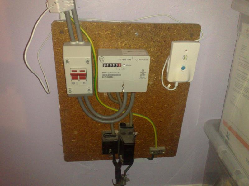
I have an RCD that keeps tripping randomly - Maybe 2/3 times a day.
I have done all the usual and unplug everything - it still trips.

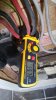
I thought I would get a earth leakage meter, I'm having trouble understanding the results (I have noticed that if I turn the unit the other way on the same pair of wires it tends to half the result).

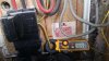
Taking a reading on the main pair - if I turn a certain 32A breaker off the reading drops a lots compare to the other breakers. I'm guess it's something on that line causing the trouble?

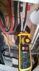
I don't get why that earth cables reads 2.5A (not 2.5mA). Is this normal?

Thanks
 

Attachments

  • 2016-02-07 13.45.58.jpg
    2016-02-07 13.45.58.jpg
    89 KB · Views: 386
  • 2016-02-07 13.46.12.jpg
    2016-02-07 13.46.12.jpg
    89.6 KB · Views: 380
  • 2016-02-07 13.46.41.jpg
    2016-02-07 13.46.41.jpg
    180.8 KB · Views: 408
Sponsored Links
Where did you get 2.5mA from? If you are getting a reading of 2.5A then 2.5A is flowing. An insulation resistance tester would be far more useful to look for tripping RCD faults. It is possible that several amps my be flowing through main bonding conductors, though I've only noticed this once. What reading are you getting from the upper earth conductor?

Edit: Don't disturb the position of those meter tails or you risk making the connections loose.
 
Do not measure the earth conductors. Measure around Line and Neutral.
Judging by the pics, the OP has done both - albeit I'm not sure what earth conductor he is measuring (there are two coming from cutout) - so, as freddo has said, may include bonding currents.

If (as in my house) the bonded water service had a low impedance to earth, it would require less than 1V between the PME neutral/earth and true earth to result in a current of 2.5A in the bonding conductor.

Kind Regards, John
 
Sponsored Links
Yes, but the current on the earth conductor(s) is irrelevant.

OP shows 123mA and 55mA leakage on tails so now needs to test (or completely disconnect) individual circuits.
 
Where did you get 2.5mA from? If you are getting a reading of 2.5A then 2.5A is flowing. An insulation resistance tester would be far more useful to look for tripping RCD faults. It is possible that several amps my be flowing through main bonding conductors, though I've only noticed this once. What reading are you getting from the upper earth conductor?

Edit: Don't disturb the position of those meter tails or you risk making the connections loose.

Thank you for the reply freddo - I was alarmed by what I thought to be a high reading for earth conductor. (I thought theoretically you only see a current on the earth conductor if there is a fault). I tried a similar thing next door and it read 16mA. So a reading of 2.5A could be fine in some cases?

I would like some help in choosing an insulation resistance tester (I'm just a keen DIYer so something under 100pounds)

http://www.amazon.co.uk/gp/product/...qid=1455058805&ref_=sr_1_2&s=diy&sr=1-2-spons

http://www.amazon.co.uk/gp/product/...ter&qid=1455058805&ref_=sr_1_12&s=diy&sr=1-12

http://www.amazon.co.uk/gp/product/...ester&qid=1455058805&ref_=sr_1_6&s=diy&sr=1-6

Thanks
 
Do not measure the earth conductors. Measure around Line and Neutral.
Judging by the pics, the OP has done both - albeit I'm not sure what earth conductor he is measuring (there are two coming from cutout) - so, as freddo has said, may include bonding currents.

If (as in my house) the bonded water service had a low impedance to earth, it would require less than 1V between the PME neutral/earth and true earth to result in a current of 2.5A in the bonding conductor.

Kind Regards, John

Thanks for the reply John - yes I have done both but was puzzled by the results. Thanks for the explanation which I will try absorb later.
 
The readings of "leakage" on the red and black tails should be the same as the reading on the grey tails ( there is no earth to the meter so no earth leakage in the meter ).

The difference 55 and 123 is probably due to the positions of the cables in the ring of the sensor and / or dirt on the face of the gap in the sensor ring core preventing it from closing properly.

As already mentioned the only reliable way to find the earth leakage route(s) is by insulation impedance measurements on both Live and Neutral of each individual circuit. The neutral must be disconnected from the Neutral bar in the CU to allow the Neutral's insulations to be measured.

Thanks for the reply - again I was puzzled by the different reading, even with my limited knowledge I thought they should be the same - but the meter is new and I don't think there was a gap. I have tested several times and I still get a big difference between the 2 sets of tails.

Any idea of a good cheap insulation meter?
 
ut the meter is new and I don't think there was a gap.
A gap of 0.1 of a mm will affect the accuracy of the measurement so a bit of grit in the gap will affect the reading. Also the two wires being compared for difference need to be as close together and in the centre of the sensor core if the results are to be anywhere near accurate for the difference in current. The reading for a wire touching the sensor core will be slightly higher than the same wire and current when in the centre of the core. The grey wires ( straight ) are a half turn in the core while the red and black ( U shaped ) are more than a half turn so will give a higher reading than if they were straight.
 
HI everyone -

1 earth leak meter, 1 insulation tester, 1 rcbo later and I have traced the problem to the living room lights.

The living room lights have 6x GU10 cheap LED's that change colour (and has a remote) - and 6x GU10 compact fluorescents. LED's are on 1 switch and compact fluorescents are on another switch.

It appears that if the LED's are left on after a while they trip. They are on their own RCD now so it's safe to say it's them causing the trouble - but what exactly? The LED bulbs? The cables? The holders?

If the figures are to be believed when the switch is off the leak current is 4mA and when the LED's are on it's 26mA.

Also I was wondering can an electrician move the dual pole isolator or add an additional dual pole isolator outside the main CU in its own mini box (you get those small boxes that can just hold 2 rcd's or 1 isolator) because even when isolator is off the main phase tail is still live.

All in all I found it difficult to trace the problem using the earth leak meter (although thinking about it, did not use it much as it was too hard to get to the pairs). It was only through the use of an RCBO and swapping various circuits in and out over a few days did I trace the problem. Was there a quicker way to do it?
 
Last edited:
Also I was wondering can an electrician move the dual pole isolator or add an additional dual pole isolator outside the main CU in its own mini box (you get those small boxes that can just hold 2 rcd's or 1 isolator) because even when isolator is off the main phase tail is still live

Do you mean like this? If so, they're really only useful if you're changing the board. Yes the live tail will be live with the CU main switch turned off, but I don't really see an issue with this. You just gotta not stick your fingers in the top of the main switch.
full
 
Also I was wondering can an electrician move the dual pole isolator or add an additional dual pole isolator outside the main CU in its own mini box (you get those small boxes that can just hold 2 rcd's or 1 isolator) because even when isolator is off the main phase tail is still live

Do you mean like this?

Yes - exactly that.
I was uncomfortable trying to get to the pairs or wire and such knowing there is live in the box. It's a metal box too. Whoever wired it made such an untidy mess. I would not have minded to swap some like mcb for rcbo but because of the live I'm not comfortable. The wires are so rigid and tangled, it cant be tidied safely without removing everything.

I was wondering what the law says? If the isolator is on the outside of the CU do you need another on the inside?
 
Last edited:
Gu10 lamps are only 2 pin hence there is no earth connection to the lamp, are the fittings earthed as most I have come across are double insulated?
Trying to move the circuit to another RCD doesnt fix the problem, it only masks it.
It is far better to get the issue fixed than to try and work around it. It could be a damaged cable, water ingress etc causing it
 

DIYnot Local

Staff member

If you need to find a tradesperson to get your job done, please try our local search below, or if you are doing it yourself you can find suppliers local to you.

Select the supplier or trade you require, enter your location to begin your search.


Are you a trade or supplier? You can create your listing free at DIYnot Local

 
Sponsored Links
Back
Top