Replace mechanical satchwell tlx 2356 with siemens rdh10rf

Joined
15 Nov 2008
Messages
21
Reaction score
0
Location
London
Country
United Kingdom
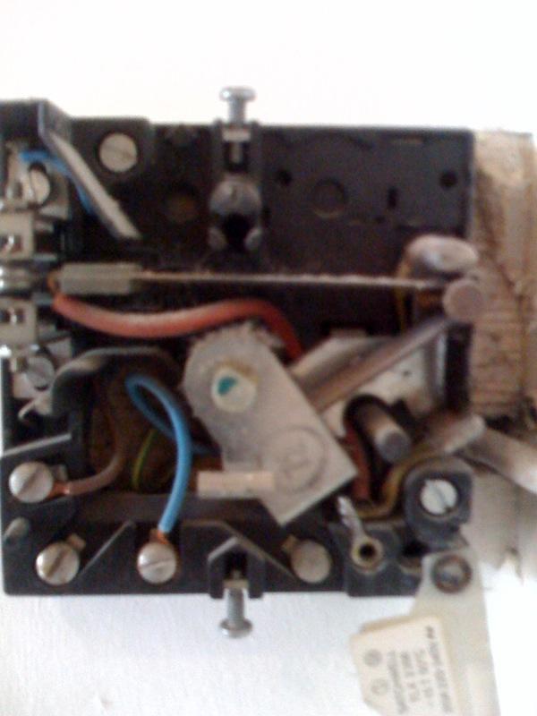
Hi I want to replace the room thermostat (satchwell tlx 2356) of my heating system, for two reasons.

1.) I think the unit is faulity (only kicking in when the dial is set to max)
2.) It is in the wrong position, it is outside of the cupboard with the boiler in it, so the temperature sensing is poor.

I have bought a siemens RDH10RF wireless thermostat.

I need some clear help/instructions on how to wire this device to my existing wiring.

The siemens has the following terminals
LX = cOMMON
L1 = Live feed to item to be controlled
L2 = Changeover contact
L = Live
N = Neutral.

Before starting this mini project, I thought (and still hope) this would be a straightforward swap over. It probably is, but I am getting lost in all the other thread which are considering programmable aspects etc.

I am hoping that all am I required to do is just change the room thermostat, and there are no other considerations?

Please help
 
Sponsored Links
You need to start by finding out exactly what you have there at the moment, i.e. how many wires, what each wire does and how it connected in.
 
My plan was that I would just swap the terminals/triggers on to the terminals in the new device.

My setup at a very high level is as follows:

I have a british gas model up1 ch & hw timer/programmer, which is controlling a boiler and a tank (which is also an emmersion heater)

The satchwell TLX 2356 that I want to replace, as far as my limited knowledge will tell me, is just acting as a room temperature thermostat controller.

From the instruction manual for the old thermostat

https://www.tlc-direct.co.uk/Technical/DataSheets/Sunvic/TLX.pdf
It has for terminals

I have included a picture of my old thermostat, which appear to be wired differently but in a straight forward way


Terminal 1 has a brown (live connection)

Terminal 2 is either used or appears to have earth

Terminal 3 has a neutral connection.


Can anyone offer any more info?

It appears that it has for terminals
 
If this Siemens is like most other rf units, you will not need any of these wires at the sender unit where your old stat was.

What you will need is a permanent live, neutral, switched live from boiler/wiring center and switched live back to boiler/wiring center from the receiver unit.
 
Sponsored Links
Hi Dave

I believe the Siemens a standard unit

It is mains powered

It has a Live & Neutral terminal (which I would guess I can take as the brown & the blue wires connect to the existing sacthwell device?)

It then has the following terminals

LX = (Common) (?)
L1 = Live feed to item to be controlled
L2 = Changeover contact

I guess what I need to know is from my old existing device, what I connect up where on the new siemens.

I can't find a conversion wiring set of instructions anywhere.

Any help would be greatly appreciated.

I need to know the following:

1. Am I going down the right path, i.e is my new device capable of swapping out the old one, or is there something I am missing which is much more complicated?

2.) If it is possible, is it just a case of identifying the wires, or is it a more substantial modification?

3.) If it is a case just transferring the wires over, can anyone tell from the pic I posted, which ones should go where?


http://www.screwfix.com/sfd/i/cat/pdfs/87/p4766387.pdf
 
Your existing stat is using just live and switchlive. It may need a neutral, which could explain why it's not working correctly, some do some don't.

Looks like the new stat will need live to L and to L common.

it will need a neutral, and switch live goes to L1.
 
Hi Hairyben (great name)

Just to recap.

I haven't tried to connect up the new thermostat (siemens) as yet, just wanting to make sure I have my info correct.

The existing stat, is the original device that was put in in the 80's I would imagine and is the original wiring, and hasn't changed. The thermostat is old now, so I think is probably not doing its temperature sensing role properly. I now operates basically as an on off switch (partly to do with its close proximity to the boiler).

Okay, so where we are at the moment is that the current satchwell tlx 2356 device looks like it has a live coming in to terminal 1 (brown wire), earth or nothing on terminal 2, a neutral on terminal 3 (blue wire), and I am not sure of what the other wiring is, and this is what I need to figure out. I put a multimeter on terminal 1 & 3, and get a circuit from these two.


Given the picture I have posted, the wiring diagram for the satchwell tlx 2356, and the wiring diagram for the new siemens rf device, can anyone help me decipher which wires in my picture, should now be connected where on the siemens device.

I would imagine for starters, terminal 1 (brown wire) on the satchwell, would go to the live terminal on the siemens, likewise terminal 3 (blue wire) on the satchwell , would go to the neutral on the siemens, but can anyone help with the other wires in the picture and which terminals on the siemens they should be connected to?

Thanks again
 
the blue is probably a switchlive, not a neutral. I don't know your stats config off the top of my head but it wouldn't work at all with just a L and N, so with two active connections they have to be L and sw L. Don't put too much trust in the colours, plumbers often use the earth as a live conductor, and believe phase sleeving is for poofters.
 
True...

So from my pics, what would be your guess for connecting up the siemens, from the wires you can see in the pics... as you will have worked out by now, my level of knowledge will need an "blue wire to LX, brown wire to Neutral etc etc type explanation ;)

thanks
 
going by your stat's current connections, blue is live and brown is switchlive

or they could be connected the wrong way round.

there's no neutral there, and I think that model requires one.

I think you need a little investigative work to determine whats what, there's no simple "put this wire there" answer, unfortunately.

given your new one is a wireless, the receiver will be connected straight into the wiring center, so you won't use the old stat cable.
 
Would it be better to get a battery powered wireless stat, so that the issue of needing a neutral is eleviated?
 
Of course :)

But I guessing that the "wireless" part of the receiver setup only is between the transmitter and the receiver? As far the the central heating system is concerned, the unit is still just a switch right? Bar the issue with the neutral, it should be able to use existing wiring to use the unit as a switch?
 

DIYnot Local

Staff member

If you need to find a tradesperson to get your job done, please try our local search below, or if you are doing it yourself you can find suppliers local to you.

Select the supplier or trade you require, enter your location to begin your search.


Are you a trade or supplier? You can create your listing free at DIYnot Local

 
Sponsored Links
Back
Top