Hi,
New to the forum but have found it useful for help and advice when browsing. I've recently bought a Hive V1 for my heating and hot water so that I can control it by my phone.
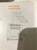
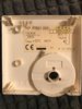
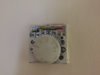
Current Setup: Potterton Boiler, Potterton EP2002 controls, Hot water tank in master bedroom cupboard.
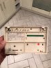
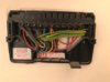
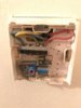
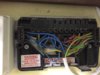
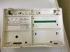
I understand the setup for the Hive but am not 100% sure about the wiring. I have attached images. I was thinking to install the hive plate with the connections from the current controls as follows:
N: All wires from Potteron [N] in plate to Hive [N]
L: All wires from Potterton [L] in plate to Hive [L] <-- not 100% sure because one wire looks like a loop from L to 5?
1: Potterton 1 is empty, this looks like its for HW off so im guessing my system doesn't require this and therefore the Hive wont?
2: Potterton 2 is empty, this looks like its for CH off so im guessing my system doesn't require this and therefore the Hive wont?
3: Potterton 3 looks like HW ON, so goes to 3 on Hive as HW ON
4: Potterton 4 looks like CH ON, so goes to 4 on Hive as CH ON
5: Dont know what to do with this, looks like its looping back to L... - there is no 5 on Hive.
Appreciate any advice given, thanks!")
New to the forum but have found it useful for help and advice when browsing. I've recently bought a Hive V1 for my heating and hot water so that I can control it by my phone.
Current Setup: Potterton Boiler, Potterton EP2002 controls, Hot water tank in master bedroom cupboard.
I understand the setup for the Hive but am not 100% sure about the wiring. I have attached images. I was thinking to install the hive plate with the connections from the current controls as follows:
N: All wires from Potteron [N] in plate to Hive [N]
L: All wires from Potterton [L] in plate to Hive [L] <-- not 100% sure because one wire looks like a loop from L to 5?
1: Potterton 1 is empty, this looks like its for HW off so im guessing my system doesn't require this and therefore the Hive wont?
2: Potterton 2 is empty, this looks like its for CH off so im guessing my system doesn't require this and therefore the Hive wont?
3: Potterton 3 looks like HW ON, so goes to 3 on Hive as HW ON
4: Potterton 4 looks like CH ON, so goes to 4 on Hive as CH ON
5: Dont know what to do with this, looks like its looping back to L... - there is no 5 on Hive.
Appreciate any advice given, thanks!