T8 Ballast Terminal Tool

Joined
27 Jan 2007
Messages
38
Reaction score
1
Country
United Kingdom
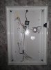
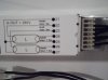
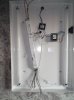
Hi, got a Osram T8 ballast to install. Could someone please tell me the type of tool used to insert the wires to the terminal and/or a link to one to see it?
I thought it was idc type but that doesn't fit. Unbelieveably I cannot find decent inf on the net about the type of tool to use.

Thanks in advance

Dave
 
Sponsored Links
Is it this type?

upload_2016-10-8_19-9-20.png
 
Hi thanks for your reply. Actually looks different to that. Its full title is: Osram Quicktronic QTP2 2x18w T8 Electronic Ballast. Pics of the exact unit now attached.Osram QTP8 - 1.jpg Osram QTP8 - 2.jpg Osram QTP8 - 3.jpg
 
Not 100% certain but someone else will know.

This is the best picture I can find.
I assume you strip the conductor - will need to be solid core preferably.
Push in from above then fold insulation down into plastic clip.

upload_2016-10-8_20-5-49.jpeg
 
Sponsored Links
But surely there should be some tool to do this? It's so similar to the way a BT socket is wired. I was originally going to open the caseing and solder wires to the terminals but when it arrived that plan has changed. If it was low voltage I'd happily shove the wire in but when it takes full mains voltage I'd like to know what the tool is. On the case it tells you how many mm of wire to strip.
Thanks again for the reply.
 
It's mains voltage but only low current.
Extra-low voltage (<50V) results in higher current. 12V is 20 times 240V for same wattage.

There are several lighting appliances with push-in terminals around now.
Plus, of course, the maintenance-free junction boxes.
 
The top slots are for when they are built in a unit and punched in with a machine tool, on the front face you will see round holes, these are for the general public to use, just strip 8mm of insulation and push in, tridonic do a tool but that is for releasing wires from the round holes
 
Not 100% certain but someone else will know.

This is the best picture I can find.
I assume you strip the conductor - will need to be solid core preferably.
Push in from above then fold insulation down into plastic clip.

View attachment 106525
I have never seen a tool to fit it would be similar to a bt or krone type tool, you dont strip the core, you would lay solid core cable on the top and punch down, im sure you know the type.
The stripping length on the unit refers to solid core used in the holes, which in the picture are not used, many fittings are now shipped out with the wires punched in and even lampholders in modules are using the punch down terminal.
i quess its quicker for them
 
No, I didn't think it was punch-down.

There is a push-in looking hole in the top. I didn't realise there was another on the front face.

upload_2016-10-8_21-59-14.png
 
Oh , maybe im wrong then, that pic does look a bit strange to the common ones i have seen, unless its the light reflecting back.
Usually its a U shape slot
It may be best if the OP posts a pic of his end on

Thisis similar, showing the 2 bottom round holes for basic use

TA_EVG_F_PC_T8_PRO.jpg
 
Last edited:
Thanks for all the replies and info.

And indeed when a solid core wire is pushed into the round terminal it does grip it. You would think this would have been mentioned on/with the ballast but no.

So, all wired up fitted, does it work? NO! There is power going through all wires as it should be, lamps checked all apparently fine. Now I think a transformer is dead. This is for a shaver socket on the mirror. Ever since the mirror was fitted I could hear a buzz from it, now, today no buzz and doesn't look like power going from transformer to socket. But I don't think that would be required for the lights to work.

I've attached some pics. I wonder what idiot thought this was a superior way to go for fluorescent lights instead of a small starter, it's a horrendous hassle in comparison. Did anyone tell the "inventor" BALLAST IS USED IN BALLOONS AND SUBMARINES!


The only wire not connected on the ballast is the last wire, as it doesn't look as though it's needed. wire 21 in the below pic.
 

Attachments

  • 1.jpg
    1.jpg
    139.5 KB · Views: 1,015
  • 2.jpg
    2.jpg
    136 KB · Views: 1,048
  • 3.jpg
    3.jpg
    138 KB · Views: 1,112
  • 4.jpg
    4.jpg
    107.3 KB · Views: 3,899
Thanks for the reply. Would connecting a wire from 21 to 22 (in the external block terminal) be correct going by the diagram on the case in this pic?
 

Attachments

  • 4.jpg
    4.jpg
    107.3 KB · Views: 550
No.

Not sure what your confusion is.
You have eight tube terminals and seven on the ballast. 21 is connected to both tubes.

Is this clearer?

upload_2016-10-9_21-34-14.png
 

DIYnot Local

Staff member

If you need to find a tradesperson to get your job done, please try our local search below, or if you are doing it yourself you can find suppliers local to you.

Select the supplier or trade you require, enter your location to begin your search.


Are you a trade or supplier? You can create your listing free at DIYnot Local

 
Sponsored Links
Back
Top