Tado installation help

Joined
7 Dec 2019
Messages
8
Reaction score
0
Country
United Kingdom
Hello,

I had a wee troll through the forums and could not find the answer to my specific question, so that's the reason for this thread.
I just bought the Tado with extension kit and am trying to install it onto my Worchester combi boiler and current Drayton Digistat SCR wireless system.

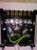
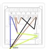
I had a look if I could just add the new tado front plate onto my existing UK standard backplate, but I don't think it is wired correctly for that (please correct me if I am wrong). So instead I was looking to rewire into the Tado extension kit. For that I was a bit confused by the channels currently used (why is channel 2 not used?) and why e.g. live is connected to channel 1 by a brown wire.

Can anyone explain to me how to wire this without blowing myself, Tado or my boiler up? Is it the potential free schedule I should be using?

If you need any more information/photos please ask.

Many thanks!
 

Attachments

  • IMG_20191207_111422.jpg
    IMG_20191207_111422.jpg
    202.8 KB · Views: 500
Sponsored Links

CBW

Joined
26 Sep 2019
Messages
15,343
Reaction score
4,880
Location
North
Country
United Kingdom
2 channel is not used because it’s controlling one channel only, the heating. Hot water is delivered instantaneously by your combi boiler. The brown wire is linked between L and terminal 1 for a common feed. What I don’t understand is why, what appears to be a switched live is connected to the common, terminal 3 appears to be switched and 4 is another permanent live? So you could be correct as in it may be wired up incorrectly. @stem and @ianmcd are very good with these.
 
Joined
7 Dec 2019
Messages
8
Reaction score
0
Country
United Kingdom
Thank you for your reply!
In attempt to clarify what is going on with the wiring for myself I have made a little diagram - maybe it's any use to any of you as well.
The cable with 4 leads at the bottom goes to the boiler. Where the black cable (with the two inner black leads) goes is a bit unclear to me. I assume the cable with the 3 wires is the mains connection.
 

Attachments

  • backplate.jpg
    backplate.jpg
    88.2 KB · Views: 395

CBW

Joined
26 Sep 2019
Messages
15,343
Reaction score
4,880
Location
North
Country
United Kingdom
Looks like @fezster is good with them as well, maybe he can get his head around it, I’m a bit lost now, sorry.
 
Sponsored Links
Joined
6 Mar 2011
Messages
194
Reaction score
35
Location
Yorkshire
Country
United Kingdom
based on your drawing the live is linked to 1 and 4?
then your have a 4core from boiler to earth neutral 3 & 4? is that correct

i would suggest that earth and neutral are common connections, term 3 is the boiler switch live for heat and as terminal 4 is unused, they have connected the browns and used as a joint for the permanent live to the boiler for controls hot water etc
 
Joined
7 Dec 2019
Messages
8
Reaction score
0
Country
United Kingdom
Thanks you both!

So I did some more demolition and traced the cables further back. The black with the two black inner cores goes to a separate condensing pump (it a condensing combi boiler). The 4 core white cable goes indeed to the boiler. The three core white cable I did not fully trace back but think it is safe to assume that is the mains supply.
That makes me wonder if channel 1 is heating on, channel 4 is heating off, and channel 3 is surplus? Or do you think it more likely channel 3 heating off and 4 surplus?
 

CBW

Joined
26 Sep 2019
Messages
15,343
Reaction score
4,880
Location
North
Country
United Kingdom
I suppose this makes a bit more sense now, thanks for the additional info. It looks like maybe:

Brown in terminal 4 is possibly used as the LS on boiler, and black go to condense pump
Neutral is NS on boiler
Black in terminal 3 going to boiler is switched live (LR?)
 
Joined
6 Mar 2011
Messages
194
Reaction score
35
Location
Yorkshire
Country
United Kingdom
Indeed it is a combi

Combi’s require both a permanent live and a switch live to operate.

Your existing receiver is connected as follows:-

On your Drayton receiver Port 1 is common, Port 2 is heat off, Port 3 is heat on and Port 4 is unused/not connected

So the 2 browns in Port 4 are using the terminal as a joint to give the boiler its permanent live to enable it to heat water

So your 4 core is earth neutral switch live(3) and permanent live(4)
 
  • Thanks
Reactions: CBW
Joined
7 Dec 2019
Messages
8
Reaction score
0
Country
United Kingdom
Does this all mean it is wired correctly and I can just put on the Tado front? No wait, in their set-up terminal 3 is unused. So I would need to rewire.
This is how Tado wants it set up (attached the Tado instructions as well)
1 COM - so that can stay the same
2 NC - heat off, stay the same
3 empty
4 NO - heat on, so terminal 3 needs to be rewired to terminal 4?
 

Attachments

  • DCAED0B9-CBE2-4098-97C9-D2483BABF3A0.png
    DCAED0B9-CBE2-4098-97C9-D2483BABF3A0.png
    495.6 KB · Views: 316
Last edited:
Joined
7 Dec 2019
Messages
8
Reaction score
0
Country
United Kingdom
Great. I am away for a few days now but will post back with whether it worked or not when I'm back.
 
Joined
7 Dec 2019
Messages
8
Reaction score
0
Country
United Kingdom
Update: I installed Tado changing port 3 to port 4 and put the 2 blacks from port 4 into a connector block. Sadly Tado does not want to fire up my boiler this way. I tried overriding the software bit to see if it is a software or hardware problem, but no activity at all yet so far. As soon as I change back port 4 to port 3 (original set up, except port 4 is completely empty as the 2 blacks are connected in the connector block) and put on the Drayton SCR front, it fires up happily. So the original idea of how it was wired still seems correct in my opinion.
Not entirely sure what my next step will be.
 
Joined
20 Jul 2005
Messages
7,419
Reaction score
1,980
Location
Nottinghamshire
Country
United Kingdom
As I figure it:

Incoming mains supply to Tado extension kit N & L

Boiler Blue wire to Tado N
Boiler Brown wire to Tado L
Boiler Black wire to Tado 4 (NO)
Link Tado L to 1

Earths to earth

Set the Tado jumper to position 1 'potential free'
 
Joined
7 Dec 2019
Messages
8
Reaction score
0
Country
United Kingdom
Thanks! That is indeed how I wired it, but no joy. Must be a software issue instead then - I'll see if Tado support can sort this.
 

DIYnot Local

Staff member

If you need to find a tradesperson to get your job done, please try our local search below, or if you are doing it yourself you can find suppliers local to you.

Select the supplier or trade you require, enter your location to begin your search.


Are you a trade or supplier? You can create your listing free at DIYnot Local

 
Sponsored Links
Top