Texecom Elite 48 remote control by WLTE relay

Joined
30 Mar 2025
Messages
9
Reaction score
0
Country
United Kingdom
I have a remote controlled sliding gate on the road side of my driveway. It is a busy narrow road and on a bend so a dangerous spot to wait and reverse onto my drive.
Almost two years ago I fitted a 4 channel 4G remote relay box, a DL4 -WLTE-EC so I can voice activate it from my car when I am two minutes away and the Gate is open when I arrive allowing me to quickly reverse in.

Once on the drive I remotely turn off the alarm before opening the garage door remotely. During the day this is very convenient.
That convenience is reduced after a certain time as my drive alarm beams are automatically made live so I have to be careful how far onto the drive I reverse.
For some time I have been pondering disarming the alarm a few seconds after operating my gate and then soon after opening my garage door. The WLTE seemed ideal for this.

In my mind it was easy. All I had to do was program a zone to be a Keyswitch. Pulsing the WLTE relays is adjustable for time as well as momentary or latching.
I mistakenly thought a keyswitch would work just like a magnetic door sensor and just use the two zone contacts.

Today I realised that is not the case because no matter what I did I could not get it to work. My simpleton idea was that a four wire device was just a pair of contacts and a tamper loop. After delving deeper in the manual for the keyswitch the drawings didn't make sense with my understanding of the detection devices. Without the wiring diagram for the panel connections it was hard to understand how one could just connect one contact to one side of the tamper. That is what the drawings seem to be suggesting. Of course I could still be misunderstanding hence this cry for HELP! (Please)

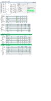
I have attached a drawing that shows a screen of Wintex. I have four areas. A is the drive beams, B is the perimeter, C is internal and D is only used as chime. Although A is timed it is only live if B is live as well. At night when occupied, areas A and B are live. C is only additionally live if the house is unoccupied.

So my questions.
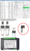
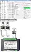
1. Do I have to connect Zone 20 contact to the tamper as in my attached drawing? If not then what am I doing wrong?
2. How long in seconds does it take the alarm to disarm after the keyswitch has operated? The messages from the smartcom seem to come a long time after the switching. I can of course test it when it eventually works
 

Attachments

  • WLTE controller.jpg
    WLTE controller.jpg
    228.1 KB · Views: 24
Can you see the zone go active? When looking at zine status.

You don’t normally program zones with multiple areas on the Premier panels, that said it should be okay for disarming zones on a key switch if I recall correctly.

Momentary switching has to see off on off.

The event log will show the time the panel registered the event, the app notification has to be recorded by panel sent out by smart com to server, interpreted and sent back out, your phone then has to pick it up, anyone of these with a poor connection can increase the delay.

You need to see how long it takes from activation to phone receiving some events.

A long time means absolutely nothing to me, a watched kettle never boils, or feels like it, but you find the water temp of water put in may affect it a little as it has harder to work.

May want to check arming modes when rearming. Also you have it down as disarm only so how you rearming it?
 
Last edited:
As you can program the time, using latch and have if off for x seconds/ minutes and then revert back, it should rearm.

There’s possibly other ways to try, but not sure things are programmed right to start with.
 
Thanks for your interest.
Probably more explanation is warranted.
My system is based on Areas and the Foyer principle.
When I go to bed I use a part arm suite ("Going to Bed") to set area B "Perimeter". Obviously my interior PIRs (Area C) should not be armed as I have to pass through different rooms. If I leave the house unattended I select a different suite ("Nobody Home") which arms B+C.
Area A ("Drive") consists of Beams and an external PIR. Area A is time armed but not active unless Area B is active as well.
There are times when it is possible for visitors to be on the drive in the morning when I am still lazing in bed so Area A is time disarmed leaving just the perimeter Area B still active. :)

I can see the resistance change in Wintex but the zone status doesn't change. The resistances are not similar to other zones. From your reply I get the impression that my original theory of how the zone 20 switching should work was probably correct. So with that in mind I did more research and discovered that I probably need resistors as in EOL wiring even though I am using double pole. Your opinion here would be appreciated.

Ref.:

I have yet to try that when I get more time , possibly later tonight.

The event log does not show anything about zone switching. Maybe it will when I get the resistors in

"Long time" was meant to refer to electronically rather than reported timing. The reason being that I need to set the timings of switching events so that I do not open my garage door before the alarm has electronically been disabled. Sorry about the lack of explanation previously.
The WLTE is quite slow on reaction times compared to the Alarm panel responses. But that can be sorted out by trial and error once the Disarm is working.

Disarm only. Rearming is not an issue or required as once the car is in the garage the alarm will not be armed again unless I go to bed or leave the house again.
 
What values are you getting for state change.

closed should be 0 and open greater than 65K (using wintex or keypad to view), other values indicate wiring issues possibly.

33k isnt uncommon when the wiring isn't right.

In your case sounds like your using the areas correctly, ie as AND, but far from the norm and if that is working as you expect then fair enough, it isn't the norm and probably a first time I have seen an example of it being applied that way.
 
Last edited:
Zone set to NO, showing active, cable Open circuit, 7.08K. Tamper linked in expander.
Zone Set to NO, showing active, cable Closed circuit, 2.19k. Tamper linked in expander. other zones showing 2.25k or 2.19k.

OOPS! sorry about the large canvas size in the pic.
 

Attachments

  • Zone 20 NC & OC.jpg
    Zone 20 NC & OC.jpg
    180.3 KB · Views: 6
Difficult to use a meter as there is a 1.4vdc across the zone contacts.
After several attempts with different settings in Wintex it seems that being active or secure is random. Which makes me think of electronic floating signals that change with the wind. Maybe that is why the resistors are needed to pull up or down.
I don't have the WLTE connected at the moment as that needs more programming so I just have a cable running from the expander to this room where I am testing from. The cable has a momentary push switch connected NO.
 
i don’t think this is wired correctly.

Firstly normally open, normally closed, eol settings are measured across two terminals, on a keypad zone and external expander first Alarm terminal last tamper terminal. Double pole is not possible on the internal expander that can be used on the 24, as it’s a zone and common only.

Your wiring is double pole, ie first two alarm pairs and tamper pairs linked out.

The resistance is interesting as what your saying is your getting 2k2 end of line and 4k7 for an activation totaling 7k, so that setting would normally be double pole /eol wiring type.

So check wiring is correct first.

But do think we have the full picture of what your currently doing so ****ing in the wind a bit.
 
I am sure you are probably correct in saying that it may not be wired correctly and that is the most likely reason for it not working.
I am confused by your references to a 24, internal expander and 33k. I do not have any of those so I assume you are referring to differences from my 48, my 2 x external 8xp and 1 x external Ricochet Wireless expander.

In my first post I asked if using the tamper wiring in my example drawing was correct. I asked this because I was unfamiliar with that configuration of wiring a zone to a tamper. As you did not answer that directly or refer back to my drawing I assumed that you agreed with my suspicion that I was mistaken and therefor reverted to standard double pole wiring as used on all my other devices.

For clarity note that only zone 20 has the tamper currently linked out at the expander and this is the area I am concerned about.
Your recent comment quote "on a keypad zone and external expander first Alarm terminal last tamper terminal." was my initial question as per the original attached drawing so I believe now that you have confirmed my first drawing zone 20 wiring. It is late now so I don't want to wake the neighbours if I get it wrong but will try the "external expander first Alarm terminal last tamper terminal" on zone 20 sometime tomorrow (or later today as it may be by the time I complete this post.

I have tried to give the full picture of what I am trying to achieve. As for "....ing into the wind a bit" I think yes we both are but not intentionally on either side as it is often difficult to explain a picture in one's head to another person. I am most grateful that you are trying to help me.
Without you I would be restricted to the Artificially illiterate AI searches which are great for general stuff but useless when you need accurate detail.
 
the drawing is fine, but the drawing isnt what your saying, your drawing, circled in red what your telling me, tamper linked out!
 

Attachments

  • WLTE.png
    WLTE.png
    536.4 KB · Views: 4
Unfortunately I can only go on what you supply, when your written description does not match your drawing.

This is why I don't think it is wired correctly. Maybe it be easier to take physical photos of what you have?
I have interpreted what you have said and drawn a diagram based on that and put it aside your original drawing.

Alas I only have your word for what you have, as for the examples, again without specifics and images I have to assume the information you give me is 100% accurate, but when your drawing and description doesn't match then i have to question do you have a metal 48 or a 48-W or a 24 (yes you be surprised how many believe they have something different to what they actually have, just because a label says so, usually people think they have better than what they have, usually ebay purchase), the hard wired expander should be an 8XP and not an 8X or an 8XE.

I personally have miss wired zones, got one leg in the wrong terminal shows up as strange value, usually on pir end because of how its being viewed and thought it was in the correct place, zone behaviour and resistance values tell me otherwise.

The resistance value is important, as it tells me more information, wires have minimal resistance a few ohms, your quoting values that suggest resistors are fitted (of 2k2 end of line and 4K7 alarm) yet using normally closed and normally open wiring types which don't use resistors. and get 0 closed and >65k open showing on the alarm panel.
 
Nothing wrong with your drawings hence why didn't comment on them (but you have examples of two terminals per zones and 4 terminals per zone (image from manual I guess). But your telling me you have something completely different to what is in the diagram.

not overly convinced my interpretation of your description is what you have, as not convinced you would get those resistance you are quoting without it being connected to a device with resistors fitted.

so I guess you have addresses 1,2 and 3 and as its hard wired zone 20, that will be address 2, and wired into zone 4 on expander address 2. I don't know that for certain but that's what your telling me.
 
Brilliant reply

A little bit of history if I may.
I left school and did an apprenticeship as a TV engineer, Black & White, 405 lines, Cathode Ray tubes, valves and pre transformers voltage droppers. I joined the RAF to be a radar technician but it soon became apparent that I was colour blind with yellow so wasn't allowed to go into electronics. A bit over the top as it was only a very mild problem that only affected colours in low light situations. I ended up as an engine technician. I left the RAF and became an aircraft engineer. I became a senior engineer and licensed on 7 aircraft types and 8 engine types in 3 countries. After a major accident in 2004 I was re-employed by the same company as a computer consultant. I wrote software for aircraft navigation and maintenance programs to aid engineers. In 2007 I fully retired on ill health from the accident. At that time I had other alarm systems but wanted something better so got my first metal Premier 48. Luckily paper manuals then. I struggled at first as the "negative logic" used confused me. A case of do this to get this or something else will be the default. With the help of people like you I became quite familiar with the Premier 48 and COMip.
Lots of things changed over the years and I generally kept up to date. I am on my 3rd Texecom panel now which is the Elite 48.
Hopefully I have given you the impression that I was fairly capable. Unfortunately around 18 months ago I had a stroke. Just one of those things that will never happen to me. Until it does! I lost a massive amount of technical knowledge which was a disaster for me. Like you I was the font of all knowledge and then suddenly dumb. It wasn't quite that bad because some of that knowledge is still in there but I am unable to access it. I have been working at recovering it but it apparently can take 2 to 10 years for the brain to relearn. The end effect is that I get things wrong until I relearn the correct way again. It leaves me unsure of myself so that I need confirmation all the time. Maybe you can see why I need to have things confirmed rather than depending on implicit

Your interpretations are generally correct. The only thing that wasn't definite is why I reverted to the incorrect wiring. My misunderstanding due to the non confirmation of my initial drawing. My apologies for that.

So the good news.

It is now wired correctly on the expander and using my temporary disarm button it electronically disarms in probably less that 1 second. So I can afford a few seconds wait time when I get my WLTE wired in again. The disarm is also shown in the log.

I am all set to continue now. Again many thanks for your help and patience.
 

If you need to find a tradesperson to get your job done, please try our local search below, or if you are doing it yourself you can find suppliers local to you.

Select the supplier or trade you require, enter your location to begin your search.


Are you a trade or supplier? You can create your listing free at DIYnot Local

 
Back
Top