Transfer from Potterton EP 3000 to a HIVE

Joined
26 Nov 2019
Messages
5
Reaction score
0
Country
United Kingdom
View attachment 176979 View attachment 176971 View attachment 176979 View attachment 176971 Hi all
I hope some kind soul out there can help with this. I am a novice but willing to learn.
The whole concept of water heating systems and electricity is voodoo to me, but I have tried to educate myself with hours of internet research and I think I am getting there but I need some help and guidance with the last bit if possible.
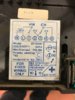
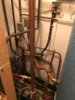
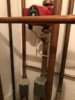
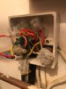
I have a Grant oil fired boiler with a separate hot water cylinder and a room thermostat.
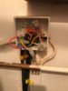
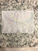
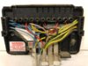
I have attached a picture of the current wiring and a schematic to make it easier to understand.
My assumptions are that;
Cable 1 - power
Cable 2 - boiler
Cable 3 - ?? Thermostat?
Cable 4 - hot water
Cable 5 - heating
My best guess going forwards to move to the HIVE is to;
Connect all N together
Connect terminal C together
Connect terminal D together
Connect terminal L together
Connect terminal 3 to Hive terminal 3
Connect terminal 4 to Hive terminal 4
Connect all Earth together.
Will this work or will I blow up?
Many thanks for anyone out there who can help :)
 

Attachments

  • img_5899.jpg
    img_5899.jpg
    293.1 KB · Views: 302
  • img_5894.jpg
    img_5894.jpg
    261.2 KB · Views: 312
Last edited:
Sponsored Links
I have tried to work out what you have, but have failed, for a boiler to do both central heating and domestic hot water (CH+DHW) there has to be some method of controlling the water flow, it could be switching a pump on for CH+DHW and not using pump with only DHW, or it could be a three port valve, or a couple of two port valves with the pump working as same time as boiler.

We refer to plans, Y, S, W, or C. In real terms these basic plans are modified slightly, but it gives on an idea of what is going on, there is no real colour code, I have even seen green/yellow which should be earth used as a live wire. However the motorised valves come with cable attached, so the core colours from the motorised valve are a real help working out what wire is what.

You likely some where have a wiring centre (not a clue why not called junction boxes) some times these are simple socket boxes with a connector block inside.

If you had a plan like this C_Plan_My_HouseD-relay.jpg it would be easy, however most plans don't show the connector strips, and even when they do rarely followed, so this Y-Plan.jpg Y-plan may show how it is done, but it may not follow the numbers shown.

So step one, have you got any motorised valves? I would assume one pump, but wiring show as example is my house with two pumps, so it may have more than one, mine is a modified C plan, but normally with two motorised valves it is a S plan, mine has no tank thermostat, but most will have one, so by noting how many ports on the valve, and how many, if there is a tank thermostat, etc, you can normally work out which basic plan is being used.

If there is a diagram on the back of the original programmer (timer) then that also helps.
 
Thank you for your quick response ericmark.
You are right about the junction box which I have now located. It looks like wires from 3 motorised valves and a pump feed in to it. Of the wires coming out, one goes to (or probably more appropriately - comes from) the hot water cylinder thermostat and the other two wires coming out bottom right go on to feed in to the programmer, presumably with the third wire going to the programmer coming from the room stat. - I have attached pictures.
There is also a pump adjacent to the boiler with the electric supply coming direct from the boiler.
I have also attached a picture of the backplate of the programmer. My understanding is that terminals A, B, C & D are just blind terminals/connectors and nothing to do with he programmer per se.
Does this give you enough additional information or do you need a wiring diagram for the spaghetti in the junction box?
Can I connect the wires to the Hive as proposed above?
Many thanks again for your help with this ericmark, or anyone else who understands these thing?
 

Attachments

  • IMG_5905.jpg
    IMG_5905.jpg
    68.1 KB · Views: 334
  • IMG_5900.jpg
    IMG_5900.jpg
    63.8 KB · Views: 282
  • IMG_5902.jpg
    IMG_5902.jpg
    45.9 KB · Views: 306
  • IMG_5903.jpg
    IMG_5903.jpg
    50.9 KB · Views: 281
  • IMG_5904.jpg
    IMG_5904.jpg
    46.5 KB · Views: 262
The EP connections are

ep-jpg.160969


and the Hive connections are

hive-jpg.160971


As you can see they are identical, except that the EP has a terminal (5) that has a wire linking it to the (L) terminal. The Hive already has this connection made for you internally, so you simply loose the link wire between the EP (L) and (5), then the remaining wires transfer from the EP to a Dual Channel Hive like for like. [N, L, 3 & 4]

The other terminals A to D as you have figured are just there as handy terminals, they have no function other than to facilitate the connection of the wires that are in them. The same is true of the earth and neutral connector bars on the right and left.

I would sink a single back box in the wall to contain all of the extra terminations and just bring the N, L, 3 & 4 connections into the Hive receiver. [If it's a metal box don't forget to make an earth connection to it]

Any existing room thermostat should be decommissioned properly by removing it and linking the switching wires together to complete the circuit. This is done by bridging the two live switching wires after removing them from the terminals. To do this you will have to trace the thermostat cable back to its origin and find out where it is connected into the circuit. Or alternatively set the original thermostat it to its maximum setting and leave it in place, so that it doesn't override the Hive.

I'm not sure why you have 3 motorised valves, unless two of them are being controlled by the same room thermostat. However, if it works now, it will work exactly the same with the Hive. Electrically speaking you won't be changing anything at all, just exchanging a couple of simple on/off switches (CH & HW) for a couple of identical on/off switches.
 
Last edited:
Sponsored Links
Thanks stem, I appreciate your response. I think 2 of the motorised valves are being controlled by the same room thermostat.
I will try the set up the Hive as suggested at the weekend and report back. Thanks also to ericmark for helping me through this too.
 
Not sure exactly what you have, but some pointers and ideas, the orignal programmer is designed for either thermo syphon or pumped domestic hot water, with thermo syphon you could not have CH without DHW and that was what the little switch was for, 10 or 16 programs, yours set to 16 so you can turn off DHW.

It seems likely you have an S Plan with two zones, but the position of the pump and valves does not quite make, maybe some radiators are thermal syphon common for bathroom to be thermal syphon.

As @stem says the hive should replace the existing, but may be the odd bit is why you wanted hive?
 
It all sounds very complicated ericmark, but thanks for the input.
I am curious why you ask why I wanted Hive? Why wouldn’t I want Hive? Why does anyone have Hive? I guess what I am looking for is more flexibility with the room thermostat, so I can move and have it in more convenient places than where it is at present, and the ability to remote access the heating so I can override the timer to give another level of flexibility. Eg if we are not going to be home until 10pm, why have the heating on at 5pm and off at 10pm?
I am curious why you ask though? I thought going ‘smart’ was the way forward?
 
I will try the set up the Hive as suggested at the weekend and report back.
Just be very careful to mark / identify the wires before you move them. There are a lot of wires of the same colour, and if you get any of them mixed up it's extremely difficult to rectify without tracing each wire individually back to its point of origin. I had to sort one out where someone had transposed a couple of wires of the same colour once. It's hard to do when on site, but even more difficult over a forum.
 

DIYnot Local

Staff member

If you need to find a tradesperson to get your job done, please try our local search below, or if you are doing it yourself you can find suppliers local to you.

Select the supplier or trade you require, enter your location to begin your search.


Are you a trade or supplier? You can create your listing free at DIYnot Local

 
Sponsored Links
Back
Top