Voltage Operated ELCB dying-What MUST be replaced in system?

Joined
6 Apr 2009
Messages
9
Reaction score
0
Location
Essex
Country
United Kingdom
The wiring in my bungalow was originally installed circa 1970.
It is relatively simple and I understand it:

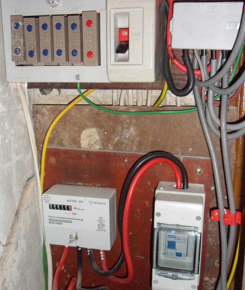
A two wire overground supply (TT) passes through a modern meter and then through an Voltage Operated Earth Leakage Circuit Breaker before branching off to wire fuse type Wylex fuse box and a more modern "garage"
single connection via a mini Consumer Unit complete with an integral Residual Current Device.
It is similar to this picture (though I don't know what the illustrated switched & fused lighting cable spur does):

voelcb_and_RCD.jpg


The VOELCB is dying, it seems to me that I would be safer if it was replaced with a Residual Current Device, though this would still turn off the whole system for any fault.
That would produce a system something like this:
/www.eec247.com/emergency/frontend_RCD_to_porcelain_fuses.jpg[/img]

Apart from the inconvenience of having no lighting,. would not an incoming RCD protect life?

If the replacement means that the whole system now has to be compliant with modern standards, ie a split consumer unit plus possible mandatory improvements in the rest of the system - what sort of expense are we talking about? Minimum adequate has always been my watch-word".
 
Sponsored Links
To correct the above link, the old circuit inside the house could be protected by something like this:

frontend_RCD_to_porcelain_fuses.jpg


????
 
although that would be very inconvenient and would not meet modern standards. Chances are if you added a single 30mA RCD onto an old installation, it would trip frequently. You might even find you were completely unable to get it to reset.

You sound like you want to avoid spending enough money to get a proper job.

The cost of a new CU will probably not be your biggest expense.

Where is your earth spike?

See if your supplier can upgrade your earth. They can often provide PME now even on an overhead supply.
 
Sponsored Links
Best I can do seems to be 500mA. The RCD today would be 300mA to cover whole house and comply with fire regulations and that's what I would do. Replace it with a 300 or a 100mA RCD as they are preferred sizes.

Yes it needs a 30mA to protect personnel but replacing a 500mA with 300mA I would class as like for like replacement. 500mA is normally for farms and you may find one.

The changing to MCB/RCBO or 30mA RCD needs a lot more work. Although I would try to get you to fit a 30mA RCD I would not want it to be the only RCD on the whole supply. And when moving from fuse to MCB/RCBO the line - neutral impedance must be taken into account so first job would be to inspect the whole system before jumping in to do any mods.
 
As an absolute minimum, the VOELCB should be replaced with a 100mA RCD.

Apart from the inconvenience of having no lighting,. would not an incoming RCD protect life?
That isn't the reason for having the existing VOELCB or the replacement RCD.
It's there to ensure the supply is disconnected in the event of a fault between line and earth.

Without it, any fault would cause exposed metalwork (such as the metal case of appliances, water & gas pips, metal sockets/switches and so on) to rise to some voltage between zero and the incoming supply voltage, which in most situations would easily be enough to kill people.
After killing someone, the power would still be there waiting to have a go at the next victim.

Even if the existing VOELCB apparently works, it still needs to be replaced as parallel earth paths in the installation can easily stop it working - and these will NOT affect the operation of the test button either, so it could still work on the test button yet be totally useless when there is a real fault.
 
The OP has got a COELCB also known as an RCD.

It's 500mA so not ideal, but better than nothing.
 
The pictures the OP has added are NOT their own installation, but something similar.
 
Yes the first picture, to which I linked is from some sort of electrical training web site and it comes complete with the annotation. The ELCB in my bungalow has a thinnish black (!) wire that loops out of the fuse box into the bottom of the VOELCB and then goes through the wall where it connects to an earth spike that has been rendered into the wall. Both the rendering and the electrics were done about 40 years ago when my shack was connected to the national grid for the first time in its 80 (now) years of existence.
The ELCB calls itself a “Henley” and has a red test button and a slider that drops down when there is an earth leak or what it perceives as an earth leak. [We are old sparring partners, but when it plays up there has always been something wrong, even if it’s a bit of bread stuck in the toaster].

When something goes wrong with any sort of system there are two questions I ask first:
What were you doing at the time ?
Has anything been changed in this system recently?

My wife was cooking a meal for all the family so the electric cooker (circa 1985) was going flat out at noon. It has a “top” oven with a grill inside. Normally it is impossible to turn on the grill and the oven at the same time. Some how she managed it and there was a “thump” and the cooker lights went out. Nothing else was turned on at the time (but see below). I was the other side of the room and dashed over to turn the cooker off at the wall.
The meter cupboard in the hall showed that the ELCB had dropped out and wisps of smoke were still emerging from it. I slid the slider up again and it stayed there. So theoretically, with the grill turned off all was solved – the objective was to get on with cooking lunch. However the cooker still would not turn on and I discovered that the 30 amp fuse had also blown. I threaded in a new wire and we were back to producing lunch.

There was a change before Xmas – you remember the fuss about PV panels and the Feed in Tariff. I had spent some “fun” time in my loft reinforcing the area over the sitting room, with the intention of getting a bargain price on the panels after Xmas – then the government tried to pull the rug away with a deadline of 11 December. I had to move fast to get the job done and ended up with a three and a quarter man team, who did the job between 11:00 and about 16:00 though cleaning up and reloading the van took another hour and a half. The garage extension mini Consumer Unit is the go between for the inverter. Two and a quarter of the team claimed to be qualified electricians and claimed the inverted needed a better earth and so drove one through the floor to serve the inverter and it was also strapped to the rising main.
Would I be right in thinking that this is an error of judgment. The water main that runs into the house is plastic and then becomes copper.

Would I be right in thinking that the short to earth in the cooker arrived back at the fuse box and then was faced with a choice of routes. As some tried to trigger the ELCB the majority of the surge ran along the earth that goes to the immersion along the pipe to the bath mixer tap, along the cold pope to the rising main and then down the new strapped earth into the new earth rod. The lack of a definitive voltage drop through the ELCB meant it was slow to act and had time to overheat and produce smoke!

I realise that the present situation is unsatisfactory and my installation needs as a minimum some sort of RCD to disconnect everything. Hopefully before a human is killed or the heat starts a fire? The inverter is designed to shut down automatically if it cannot recognise that there is a grid connection

Any thoughts on the costings of your various suggestions?

Is it still possible to buy a free standing RCD and breaker that could be installed between the meter and the fuse box?

Would the possibility of current flowing in both directions get it confused?
 
The pictures the OP has added are NOT their own installation, but something similar.
Harry - the point of you posting a photo which is

a) not of the installation you're asking about

b) wrongly annotated anyway

was what, exactly?

:rolleyes:
 
. The ELCB in my bungalow has a thinnish black (!) wire that loops out of the fuse box into the bottom of the VOELCB and then goes through the wall where it connects to an earth spike that has been rendered into the wall.
Voltage operated without doubt.

The meter cupboard in the hall showed that the ELCB had dropped out and wisps of smoke were still emerging from it.
It's totally destroyed, get it replaced immediately.

Is it still possible to buy a free standing RCD and breaker that could be installed between the meter and the fuse box?
Would the possibility of current flowing in both directions get it confused?
Yes, and it's just an RCD. Current flow is irrelevant, it's an AC circuit.

Any thoughts on the costings of your various suggestions?
To remove the obviously destroyed VOELCB and install an RCD & enclosure should be less than £100.
Other work may be required, such as fitting a proper earth rod (they are installed in the ground, not cemented into a wall.) Impossible to price that without seeing it.


To avoid any doubt:
1. Your installation is dangerous and needs to be repaired as soon as possible.
2. This is NOT the kind of work you or any other DIYer should be attempting themselves.
 
Many thanks flameport, you have convinced me that I need a second (professional) opinion.

[Mind you the guy who fixed the extra earth to my rising main is NICEIC registered - In my life time I have had disagreements with 5 so called professionals, where it turned out I was right and they were wrong to the tune of money totalling 7 figures in total.
I am not saying I have some superior intellect it was just that they were operating in "blue @rsed fly mode", whereas the situation was personal to me; I had hours/days/months to mull over what was happening and arrived at a different conclusion.]

I completely agree with you that I am probably living in a home that could have bare metal at a potential of 240 Volts and requiring 30 amps to blow the fuse. [wear a hat & touch anything metal with knuckle side of your hand first ?] :!:

Can I ask two more questions:

- There is a rumour doing the rounds that a PV system should have its own earth capable of dumping 400volts DC to ground in an emergency; it ties in with another rumour that firemen are getting a bit "twitchy" about rushing into a burning building with a glass plated roof trying to churn out the DC equivalent of 4 kWp at 400+ volts.
Any truth in the rumour mill or is it all urban myth ready to appear on "snopes"?

- While trying to assess the suitability of my home for PV panels, I borrowed a gizmo, that plugged into a 13 amp socket and ran through a series of tests, then displayed results as a series of coloured lights on the front. It supposedly measured the resistance to earth and had green lights for (say) 3 ohms, 5 ohms, and 7 ohms, the next light was 10 ohms and this and higher lights were red. My earth, through the VOELCB and the earth spike covered with render, lit up the 10 ohm failure light.
Are you surprised?

I will let you all know how I get on trying to get the installation "safe" again.
 
- There is a rumour doing the rounds that a PV system should have its own earth capable of dumping 400volts DC to ground in an emergency; it ties in with another rumour that firemen are getting a bit "twitchy" about rushing into a burning building with a glass plated roof trying to churn out the DC equivalent of 4 kWp at 400+ volts.
Any truth in the rumour mill or is it all urban myth ready to appear on "snopes"?

Sounds like a load of old nonsense to me.

First of all it is not possible to just 'dump electricity to ground' when it is not wanted / required.

Second of all I don't see how having a solar panel on the roof is any more of a hazard than a couple of tones of roof tiles, and as for there being electriciy present from the solar, well there's already a large electricity supply into virtually every building in the country anyway.

- While trying to assess the suitability of my home for PV panels, I borrowed a gizmo, that plugged into a 13 amp socket and ran through a series of tests, then displayed results as a series of coloured lights on the front. It supposedly measured the resistance to earth and had green lights for (say) 3 ohms, 5 ohms, and 7 ohms, the next light was 10 ohms and this and higher lights were red. My earth, through the VOELCB and the earth spike covered with render, lit up the 10 ohm failure light.
Are you surprised?.

No that is perfectly normal with a TT supply.

A theoretical Ze of upto 1666Ω is allowed on a TT supply, but the value should really be sub 100Ω to ensure reliability of the connection.

Of course readings this high are only permitted when there is a properly functioning RCD(s) in the installation. With out this, the installation is a genuine immediate risk to you and your family and MUST be repaired without delay.

I don't think you realise just how dangerous things are at the moment.
 

DIYnot Local

Staff member

If you need to find a tradesperson to get your job done, please try our local search below, or if you are doing it yourself you can find suppliers local to you.

Select the supplier or trade you require, enter your location to begin your search.


Are you a trade or supplier? You can create your listing free at DIYnot Local

 
Sponsored Links
Back
Top