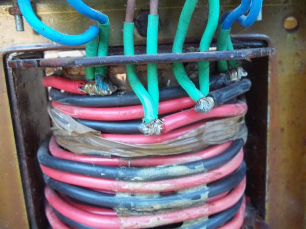
Winding transformer

The main risk is that the transformer outputs a high voltage but also at a reasonably high current - easily enough to kill. ... Most other easily available high voltage sources such as CRTs have very limited current capability.
As I think I've reported before, I came across one potentially-lethal exception to that back in the 60s - a TV with model number "TV1" (I forget the make), in a floor-standing mahogany cabinet, which had a mains-driven EHT supply for the CRT (rather than the usual voltage tripler fed from the line output transformer, which has very low current-supplying ability).

Kind Regards, John
 
Sponsored Links
Thanks for all the replies.

To all of the answers that haven't gone off into the KV stratosphere. I need to calculate the windings for the secondary, also the cost, as it would be fairly thick wire, I imagine. If you've done it before, is it hard to feed the wire through the loop, while keeping the insulation in tact?

I've yet to look inside the microwave to make sure that the transformer will lend itself to being rewound.

Camerart.
 
To all of the answers that haven't gone off into the KV stratosphere. I need to calculate the windings for the secondary, also the cost, as it would be fairly thick wire, I imagine.
You could only directly calculate the required number of turns for the secondary if you knew the number of turns in the original secondary (and the voltage the transformer was designed to produce - which may well be marked on it) - if, for example, the present secondary had 1000 turns to produce a 2000V output, you would need about 12 turns to get a 24V output. However, since you would almost certainly have to totally destroy the present secondary to get it out, you're unlikely to be able to count the turns (even if you were very patient!).

In practice, therefore, you would probably have to determine the answer by experiment - remove the secondary and replace it temporarily with, say, 5 or 10 turns (of any insulated wire) and measure what voltage you get. That will give you the "turns/volt", from which you could calculate the required number of turns for your desired output voltage. For example, if 10 turns gave you 18 volts and you wanted 24V then the number of turns required would be about (10 x 24 / 18 ), namely 13.3 turns, so you would probably use 13 or 14. Then remove the temporary secondary and replace with one with adequately fat wire for the current you will be talking about.
If you've done it before, is it hard to feed the wire through the loop, while keeping the insulation in tact?
With the small number of turns you're likely to need, it should not be a problem - I would think the main problem would be in removing the present secondary without damaging anything else (like the primary!) - some of the on-line descriptions talk about using an angle grinder to remove the secondary!! If you Google "rewind microwave transformer" (without the quotes) you will find lots of stories, and some videos, of people who have done more-or-less what you want to do, often to create transformers for welders
I've yet to look inside the microwave to make sure that the transformer will lend itself to being rewound.
That could be an issue, but the on-line articles and photos/videos seem to suggest that it's usually possible. The material BAS linked to suggests that there are only about 4 different manufacturers of such trannys in the world, so they are probably all very similar.

Hope that helps, but I still do wonder whether you really should be doing this!

Kind Regards, John
 
Thanks John,

Very informative.

Will the rectifier, and regulator circuit, affect the calculation? I need DC.

C.
 
Sponsored Links
Thanks John, Very informative.
You're welcome.
Will the rectifier, and regulator circuit, affect the calculation? I need DC.
You would need to dump the existing high voltage rectifier and capacitor and replace them with some suitable high current low-voltage rectifier (probably a bridge rectifier) and a high value (lower voltage!) capacitor. As for regulation etc., that depends upon what you want - battery charger regulators can be quite sophisticated these days, but might be almost non-existent - those interesting in welding etc. obviously don't have much interest in regulation!! A 24V RMS output from the transformer would theoretically give you something approach 34V 'raw DC', off load, from the rectifier/capacitor to feed to a regulator. How much voltage you needed would depend entirely on the regulation arrangements. If you were going to have little regulation, you'd probably want a lot less than 24V coming from the tranny. You would need a fair bit of knowledge to design an appropriate regulator

Kind Regards, John
 
I still do wonder whether you really should be doing this!
blank_65x10_T.gif
plus_one.gif
 
You haven't said what type of battery you are planning to charge?

Ni-cam, Ni-Mh, Li-ion batteries will be quite specific with their charge requirements. Plain old lead acid (boat, truck etc) may be more tolerant, but charge voltage will need to be more than 24v. Probably in the range 27-30ish volts.
 
You haven't said what type of battery you are planning to charge? ... Ni-cam, Ni-Mh, Li-ion batteries will be quite specific with their charge requirements. Plain old lead acid (boat, truck etc) may be more tolerant, but charge voltage will need to be more than 24v. Probably in the range 27-30ish volts.
Indeed - as I said, everything depends upon what sort of regulation etc. he requires. I suspect, however, that he is talking about "plain old lead acid", since he would probably have to be too rich to be even thinking about re-winding transformers if we were talking about any of the other types of battery that needed 40A charging current!

If it is lead-acid then, as I said a 24V (RMS) secondary should give him in excess of 30V off-load with a setup which had little/no regulation.

Kind Regards, John
 
Plus, ISTR, any type of battery benefits from the right sort of intelligent charge management, including good old Pb-H2SO4. .... Just banging a fixed voltage onto a battery is not necessarily a good, or even reasonably good idea.
Indeed - as I wrote ....
As for regulation etc., that depends upon what you want - battery charger regulators can be quite sophisticated these days, but might be almost non-existent ... How much voltage you needed would depend entirely on the regulation arrangements. ... You would need a fair bit of knowledge to design an appropriate regulator
Kind Regards, John
 
I remember going through the formula in Uni for working out number of turns but my son has all my books so can't look it up.

However although you can hand wind it would seem rather pointless.

The problem is the efficiency of the transformer. For an old battery charger the transformer was very poor. It relied on voltage decay under load to reduce charge rate as the battery became charged.

At 40 amp there are two types of charger. There is the simple type designed to help start a wagon so at cranking voltage say 20 volt it will give 40 amp but under normal conditions it will give somewhere between 5 ~ 15 amp.

The second type is designed to charge a battery as quick as possible without damaging the battery. These are again split into two rough groups.
1) The stage charger designed to charge a battery which is not being used.
2) The pulse charger designed to charge a battery which is being used at the same time.

Up to now talking about lead acid batteries as we move to alkaline batteries the methods are different. The two common methods are:-
1) Delta V
2) Temperature

Rarely is a 24 volt battery actually 24 volt lead acid are often 30 volt.

Since most transformers have a sin wave output a 24 volt transformer can actually still charge a battery at 33.5 volt with full wave rectifier so it's not that simple.

I remember back in the early 1990's trying to charge caravan batteries but not over charge them. I found to buy a 16 volt transformer which would have been ideal was more expensive than buying a standard battery charger but the latter would overcharge the battery.

The answer was instead of controlling output I turned the excess into heat. Wind chargers have done this for years.

So what battery do you want to charge and what are you using the battery for? Today switch mode power supplies use high frequency transformers which mean they are far smaller so often now cheaper to buy ready made than make your own.
 
can some one enlighten ime what tran is in a microwave and why please.
also is there a risk in going in the thing to actually get it out

As far as I know, it ok to open the box, radiation wise, as long as you pay attention to charged capacitors. (I'm no expert!)

IT MUST BE DISCONNECTED FROM POWER!!!

C.
 
No-one here so far seems to know the one property of a Microwave Oven Transformer which makes it different to other types of transformer.

All MOT's have a magnetic shunt in the core which makes the transformer a high impedance source. This additional impedance self-regulates the current through the magnetron.
In some MOT's this shunt can be physically removed but not all.

I would say that in general, a MOT is not is suitable for a re-wind.

Frank
 
I think I used the wrong term! When I said regulator, I should have said All I'm after is a sabilise power supply.

C.


Thanks John, Very informative.
You're welcome.
Will the rectifier, and regulator circuit, affect the calculation? I need DC.
You would need to dump the existing high voltage rectifier and capacitor and replace them with some suitable high current low-voltage rectifier (probably a bridge rectifier) and a high value (lower voltage!) capacitor. As for regulation etc., that depends upon what you want - battery charger regulators can be quite sophisticated these days, but might be almost non-existent - those interesting in welding etc. obviously don't have much interest in regulation!! A 24V RMS output from the transformer would theoretically give you something approach 34V 'raw DC', off load, from the rectifier/capacitor to feed to a regulator. How much voltage you needed would depend entirely on the regulation arrangements. If you were going to have little regulation, you'd probably want a lot less than 24V coming from the tranny. You would need a fair bit of knowledge to design an appropriate regulator

Kind Regards, John
 

This is one I did earlier. ( around 1990 ) to supply 12 volt AC to 200 lamps of 2.2 watts each for outside Christmas lights.

Two secondaries wound using old cooker cable.er

The donor transformer was from an industrial stepper motor driver system. ( one kilowatt if I recall correctly ) with four 70 volt secondary windings

Note the burnt out terminal. the 70 volt terminals should have been changed for larger ones to cope with the higher current
 

DIYnot Local

Staff member

If you need to find a tradesperson to get your job done, please try our local search below, or if you are doing it yourself you can find suppliers local to you.

Select the supplier or trade you require, enter your location to begin your search.


Are you a trade or supplier? You can create your listing free at DIYnot Local

 
Sponsored Links
Back
Top