2 gang switch to control 2 lights

Joined
29 Oct 2013
Messages
14
Reaction score
0
Location
Devon
Country
United Kingdom
Hi,

I hope someone can help me pls.

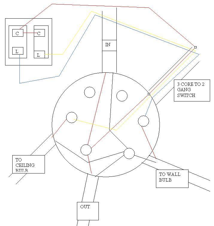
I have a ceiling rose in my lounge and two wall lights. Each are controlled independently by a 2 gang switch.

The current arrangement is a cieling rose, which has 4 wires coming into it.

2 wires 1mm t+e are the feed in and out, 1 wire (3core) goes to the switch and the fourth wire feeds the wall lights.

the 1st wall light then has another wire 1mm t+e coming from it to the other wall light.

All floor boards above are up so all wires are visible.

I am laying tongue and groove floor instead of floor boards so i would like to use junction box wiring system to minimise wiring under the t+g floor.

I would like to use junction box wiring for all downstairs lights (with all JB's located in one central spot with an access panel in floor)

is it possible to incorporate this into a junction box so that i have minimal wiring under the floor. i.e one switch wire going to ceiling rose and one switch wire going to the wall lights.

I would like to maintain the use of the 3 core wire as the conduit running down to the switch only allows for one cable to be feed down it. Otherwise i would have gone for 2 junction boxes and two independant circuits.

Does that make sense?

I found a post doing this yesterday but can find it today :(
 
Sponsored Links
The best method is avoid junction boxes and have all the terminal connections/joints entering the accessories (switches and light fitting)
Then you always have ease of access to connections.

If this is unavoidable, then maintenance free methods of jointing would be required, for joints hidden under floors.
 
But if i wanted to do it with junction boxes would it be possible and if so how would i wire in the 3 core cable from switches?

The junction boxes will be accessible so this shouldnt be an issue
 
Presumably it works as it is; why do you want to alter it with unnecessary junction boxes?

Why would you want an access hatch in a nice new floor?
 
Sponsored Links
I would like to maintain the use of the 3 core wire as the conduit running down to the switch only allows for one cable to be feed down it. Otherwise i would have gone for 2 junction boxes and two independant circuits.

Does that make sense?
No. They would still be on the same circuit.
 
But if i wanted to do it with junction boxes would it be possible and if so how would i wire in the 3 core cable from switches?

The junction boxes will be accessible so this shouldnt be an issue

So the three core cable is supplying both ceiling light and the pair of wall lights?

Do you have an earth core present or is the conduit acting as the path to earth?

If you wanted to do as you intend, I would think of replacing the 3 core with 3 core plus earth.
But do not see the logic in the methods you wish to use, you have a chance with floorboard up, to make all connection easily accessible at the accessories.
 
sorry i should have said the the 3 core is 3 core and earth and yes the 3 core+earth control both ceiling light and wall lights independently via a 2 gang 1 way switch.

What i'm proposing is to put the junction boxes in the floor in the landing which will be easily accessible and have minimal wires i.e two wires coming from the junction box in landing to supply the ceiling rose and the wall light, but using the 3 core + earth wire from the switch. I'm confused on how the 3 core would link into this, thats the bit i struggling with. I take it i would need a 6 terminal junction box but only use 5 terminals?
 
By your description if I understand correctly.
The four sets of cable at the ceiling rose entry are going to be moved to a semi accessible location under floor and connected to this would be another cable to the ceiling light entry.
So you will have 4 cables (one 4 core) plus an additional cable going to the ceiling light.

So you would need a terminals for:
1) Earth/CPC
2) Neutrals
3) Live loop
4) Switch line ceiling lights
5) Switch line wall lights

The 3 core and earth cable from switch would terminate with earth core at earth, one core in live loop (that would need to be identified), then the other two in their required switch lines (ceiling/wall again would need to be IDed) terminal.

I would recommend if you are insistent on joint boxes, using two ashley 20Amp MF boxes.

https://www.tlc-direct.co.uk/Products/ASJ804.html

If this is work you are going to undertake yourself, I would suggest you learn a little about installation techniques, the understanding of electrical circuits and inspection, test and certification methods, and the results/measurements you get are compliant and safe.
 
thanks for the links

On another note, I have added extra sockets to an existing ring main. This has resulted in new and old colours mixing? Not much in old colours as there weren't many sockets to start with. Does this matter, the cables are all upvc. Should i replace or ok to leave? My friend told me that the spark when sign off electrics on extension has to tell building control a mix of colours in box?

Ok will stick with the layout i have then. I personally prefer junction boxes as find them easier to follow and results in fewer wires.

With the lighting circuit the majority of it is 1mm cable (old clours). Can i add extra lights with 1.5mm cable or should i replace the lot. The circuit have a 6amp RCBO on. If fact all circuits on the board are RCBOs.
 
Mix colours should be documented in the installation certificate and a warning notice placed at the board regarding the two version of colours.
If new sockets have been installed and cable buried in walls, there is a requirement for this cable to be routed in the permitted zones and the cable and sockets to have additional protection of 30mA RCD.

Building controls do not need to know of two versions of colours, but the installation commission document must remark upon this and a notice be displayed at the board.
 
By your description if I understand correctly.
The four sets of cable at the ceiling rose entry are going to be moved to a semi accessible location under floor and connected to this would be another cable to the ceiling light entry.
So you will have 4 cables (one 4 core) plus an additional cable going to the ceiling light.

So you would need a terminals for:
1) Earth/CPC
2) Neutrals
3) Live loop
4) Switch line ceiling lights
5) Switch line wall lights

The 3 core and earth cable from switch would terminate with earth core at earth, one core in live loop (that would need to be identified), then the other two in their required switch lines (ceiling/wall again would need to be IDed) terminal.

I would recommend if you are insistent on joint boxes, using two ashley 20Amp MF boxes.

https://www.tlc-direct.co.uk/Products/ASJ804.html

If this is work you are going to undertake yourself, I would suggest you learn a little about installation techniques, the understanding of electrical circuits and inspection, test and certification methods, and the results/measurements you get are compliant and safe.

Yes thats exactly what i'm after. so 2 cables under the bedroom floor rather than 4! would you be able to post me a diagram of exact arrangement.

My electrician friend checks everything i do. I just like to check i got it right in my head before i start or ask him for help / to check. He has helped me loads and i dont want to take the mickey by constantly asking
 
Ok will stick with the layout i have then. I personally prefer junction boxes as find them easier to follow and results in fewer wires.
I don't!
With the lighting circuit the majority of it is 1mm cable (old clours). Can i add extra lights with 1.5mm cable or should i replace the lot. The circuit have a 6amp RCBO on. If fact all circuits on the board are RCBOs.

If there is nothing wrong with it, what need to replace.
You can add extra lights with both 1.00mm and 1.5mm. I try to keep to the same CSA throughout the circuit though!
 
Ok i think i got this, is this right?

AT 2 gang switch:

3 core cable and earth (red, yellow and blue)

Common - red wire (link wire to connect both switches)
L1 - switch wire for Wall light - Blue
L2 - switch wire for ceiling light - yellow
Earth to metal box

6 way junction box:

Pt 1:

Red wire from feed in, Red wire from feed out, Red wire from 3 core - switch wire

Pt 2:

Black wires from feed in, feed out, wires to ceiling light and wall light.

Pt 3:

All the earths joined together and sleeved

Pt 4:

Red wire to ceiling light and yellow wire from switch

Pt 5:

Red wire to wall light and Blue wire from switch


I have used old colours as thats what i have at present. Might have got my reds and blacks round the wrong way?

Is the configuration right?
 

DIYnot Local

Staff member

If you need to find a tradesperson to get your job done, please try our local search below, or if you are doing it yourself you can find suppliers local to you.

Select the supplier or trade you require, enter your location to begin your search.


Are you a trade or supplier? You can create your listing free at DIYnot Local

 
Sponsored Links
Back
Top