Adding external light to electric garage door opener

Joined
1 Jul 2014
Messages
156
Reaction score
7
Location
Hartlepool
Country
United Kingdom
Hi, I have a GRD+ Gliderol motor on my roller garage door. I want to fit an external light that is connected to the motor so when it activates the light comes on.

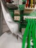
There is a 3 pin connection on the main PCB within the motor housing which states it is for an external light. However, I believe I need another PCB to plug into this connection to get this up and running. Question is can I connect directly to the 3 pin connection without adding another PCB and if not where can I get the PCB as I've searched everywhere and they don't seem to be available?
 
Sponsored Links
Depends on what that 3 pin connection actually is, but it's unlikely to be for connecting another light directly.

Probably for an external relay, with the contacts of that relay used to control another light or whatever else.
 
Thanks guys.

I agree it's not just a simple connection and therefore requires an add on PCB, problem is I have literally searched the globe and can't find one or even one from another manufacturer that I could use.
 
Sponsored Links
As it is showing three wires I bet / guess the three wires are:
GND
12V dc
Signal (ie 12V on or off).

And if that is the case then this module will be the same as you are looking for (note that it needs to be in a box if you use it to switch 240V).

https://www.ebay.co.uk/itm/1-channe...378827?hash=item25f2dd4acb:g:4a0AAOSwb9BaymBV


Can you confirm this is the correct pinouts wiring?
Can you look at the motherboard and see if one pin is GND, see if the other pin is 12V and see if other is signal (it is sometimes written on board).

Do you have a multimeter to test it?

SFK
 
Links in this post may contain affiliate links for which DIYnot may be compensated.
My pleasure.

Note that II did not answer your question. You cannot connect directly to the 3 pin connector to switch a 240V light. You will need a relay.
You might be able to use it to connect to a low power 12V light, but I would be worried that it will not be designed to take this extra load.

Also this is a better manual.
https://www.gliderol.co.uk/content/G+_operator_instructions.pdf
or from the manufacturer.
https://www.gliderol.com.au/wp-cont...RD-Owners-Manual-amp-Install-Instructions.pdf

Would be interested to see a photo of the circuitboard as well.

SFK
 
Last edited:
Hi SFK, understood, thanks.

I've took a photo but I couldn't see any markings adjacent to it.
 

Attachments

  • 20210209_174043.jpg
    20210209_174043.jpg
    192.4 KB · Views: 211
Shame.
My guess (if they are consistent looking at other connection) is that left is 12V, middle is GND and right switched 12V.
As said it is a guess, but that is how I would test if you have a multimeter.
SFK
 
Hi SFK, I tested the contacts, using the far left and far right contacts and I'm getting 12v so I'm guessing the middle one is the switched live, would you agree and if so would the module in the ebay link do the job?
 
My electric door had a light in its unit, i simply found the two wires to the lampholder and paralleled off them to a relay of the same voltage, capable to switch mains voltage
 
It would be sensible to confirm (carefully) with your meter that the centre pin does change state with motor running- it may just pulse at motor start rather than being high while motor running.
Doesn't make the job impossible, just means you'd need a delay relay (which would make total sense of the permanent 12v on that connector)- you're looking for off delay (where the relay once triggered latches for x seconds)
 
Very good point from oldbutnotdead.
My assumption was that Switched 12V would be on for as long as the onboard LEDs (I actually assumed it was the same wire - in a similar vien to 333's suggestion).
But as oldbutnotdead said it might just be a pulse.
Can you safely test this?

Otherwise, get the relay module, wire it into the 12V, OV and switched live (but not the side 240V yet) and listen to see if you can hear the relay switch as you activate the door (or use multimeter in the relay output blocks, set on continuity and listen to the multi meter beep).

If it is only a pulse you need a 'timer relay module".
And you need the type with three inputs - 12V GND and Switched 12V
Like this: https://www.ebay.co.uk/itm/New-12VD...144375?hash=item1c7e2083b7:g:svgAAOSw~AVYtW9x

SFK
 
Links in this post may contain affiliate links for which DIYnot may be compensated.

DIYnot Local

Staff member

If you need to find a tradesperson to get your job done, please try our local search below, or if you are doing it yourself you can find suppliers local to you.

Select the supplier or trade you require, enter your location to begin your search.


Are you a trade or supplier? You can create your listing free at DIYnot Local

 
Sponsored Links
Back
Top