HELP NEEDED WIRING LIGHT FITTING

Joined
20 Aug 2019
Messages
6
Reaction score
0
Country
United Kingdom
Hello all,

So this is my first post and I need some advice as I think this is probably an obvious mistake I'm making so I'm hoping someone should be able to help! I'll try and keep this as simple as possible and I've attached a few photos for clarity! In short this is the situation.

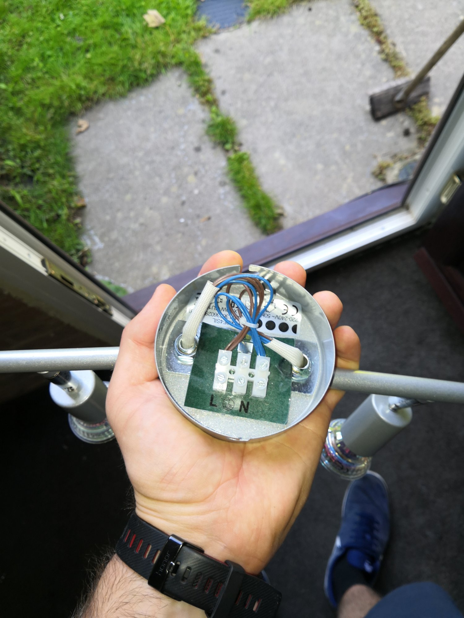
1) I'm replacing a standard Batten light in our garage with a 4 bulb living room style light fitting.

2) This light has previously been operated by one of two switches (one in the garage itself, and the other in the adjoining kitchen)

3) When I disconnected the old batten light and removed it I stupidly didn't take a picture of the wiring.

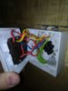
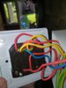
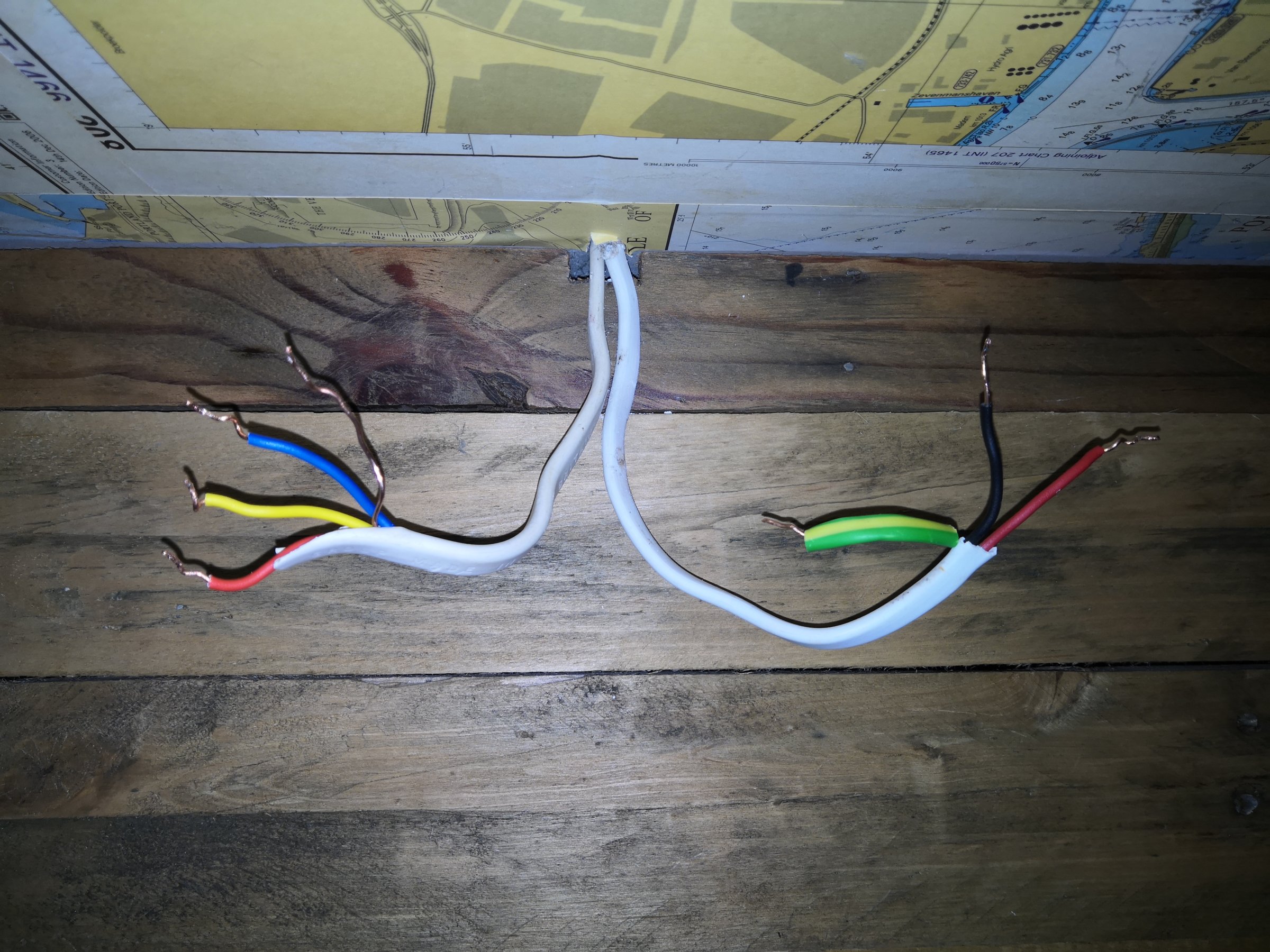
4) Out of the ceiling are two white cables (pictures attached) one has four wires inside it and the other 3. I think the cable with 3 core wires inside it goes on to operate the outside Pir light and the one with 4 wires opearates the garage light. I'm assuming at this stage that the additional 4th wire which is yellow is for the 2 way switch?

5) When replacing it I wound both live wires from each of the white cables together along with the yellow and screwed that into the Live terminal on the light fitting. Then wound both neutrals together and screwed them in and then wired both earth's and did the same.

6) When I turned the power back on the light was on and couldn't be turned off by either of the light switches. I've tried a few different combinations but can't get the switch to work??


With general DIY I've got a decent basic knowledge however as you can probably tell when it comes to electrics I'm a total amateur. Before I get to the stage where I'm calling an electrician to come round and show me the correct order to put the wires in and then charge me a small fortune I thought I'd see if anyone on here has a better understanding.

Many thanks in advance for any words of wisdom!!


Gilo
 
Sponsored Links
Do you have any testing equipment ,multimeter maybe ?
Guessing isn't really a good idea. I suspect that the three core and earth has the following conductors..
Permanent line (red)
Switched line ( yellow)
Neutral ( blue )
And of course the cpc ( bare earth conductor)
The twin and earth ,if you are correct ,supplying the outside pir.
Your light fitting was permanently on because you connected it to the permanent line , only the switched line ( yellow )should connect to the fittings L terminal ,and the neutrals both connected to the fittings N terminal. Both earths connect to the fittings earth terminal.
The permanent line ( red )should go in a separate connector block together with the red from the twin and earth ,and this should not connect to the light fitting ,but should be insulated from it.
Really the conductors need to be tested to establish which is which ,but with the info you have given above ,(and you made no mention of blowing fuses or tripping MCB' s ,so I ASSUME YOU DIDN'T) I Think the above is the way it should be wired.
 
Can you post a pic of the wiring at the two switches?

Did the pir work when the garage light was disconnected?

Did the garage light work from each of the two way switches?

Blup
 
Does the outside PIR light have a switch controlling it or not?
 
Sponsored Links
To everyone who has replied I'm really grateful and sorry its taken me so long to get back to you, work has been a little mad a the last few dayst. So to answer your questions this is where I'm at:

Terryplumb- No, I don't have a multimeter currently, however tomorrow morning I'm off to Screwfix to get a Fluke Voltage Tester. As you've said the yellow is likely to be the switch line so I want to confirm this.

As for tripping, in the configuration I mentioned originally none of the fuses went and all seemed OK other than the fact the switch didn't work, which makes sense as you've said I've screwed in the permanent live! I understand what you're saying about the two remaining permanent live wires going into a connector block but what I can't visualise is where this block goes. Does that also go inside the light fitting assuming it'll fit and can be fully insulated? Sorry this is probably obvious but as I've mentioned this is not something I'm an expert in and grateful for all the support!

Blup- Yes, I'll definitely send a picture tomorrow when I'm going to do some more investigation around it.

As for the pir, yes when I connected the garage light fitting as I mentioned originally the outside pir worked no problem and reacted to movement!

As for the garage light working if you mean before I changed the old batten light then yes both kitchen and garage switch would activate the light in and off. As I've said though when I rewired it like a total moron the light came on and stayed in permanently with no change from either of the switches.

Securespark- Just lieknive said to tehnothers thanks for your interest and help.

Yes, although the outside light is a pir you can override this with the switch inside the garage. One thing I havn't mentioned which may or may not be relevant is that the light switch in the garage has 3 switches, one to operate the garage light, one to operate the outside rear pir and one to operate the front of the house (garage door).

Thanks to all and I look forward to your responses!
 
The fluke tester that you intend to buy ,is it a non contact voltage sensor ?
The permanent line conductors can be within the light fitting ,but not connected to the fitting. ( So a separate connector block required )
 
Better to buy a 2-probe tester. Those magic wands are ok to detect the presence of a live conductor, but that’s only half of the circuit.
Many faults are due to faulty neutral connections and you’ll need a two probe tester, or a multimeter to find that.
 
So I've bought a multimeter following your advice about that and I'll update shortly! Next action is to learn how to use the thing!!! It's this one for info, I havn't gone mad in price as I'm not convinced I won't end up calling an electrician in the end!
 

Attachments

  • 15665560079055160266874145285717.jpg
    15665560079055160266874145285717.jpg
    185.5 KB · Views: 291
So update.......

Using the multi meter the 3 core cable on the right has about 230 volts passing through which is unaffected by any light switch combinations.

The 4 core cable on the other hand has nothing whatsoever. Neither the live neutral or switch live seem to have any volts passing through?

I know when I first started trying to wire in the light fitting and then tested it at one point the fuse tripped and power switched off immediately. I'm now wondering if I've blown something in the cable or burnt out a wire or something??

Any thoughts or ideas greatly received!!!

Thanks again
 

Attachments

  • IMG_20190823_122226.jpg
    IMG_20190823_122226.jpg
    207.1 KB · Views: 278
  • IMG_20190823_122220.jpg
    IMG_20190823_122220.jpg
    187.2 KB · Views: 287
  • IMG_20190823_121749.jpg
    IMG_20190823_121749.jpg
    278 KB · Views: 287
You keep saying "the switch in the garage" and it now turns out there are three.

Unless you can describe better how the system operated, then, I think, you will require an electrician.
 
Yep correct, three individual switches, when I say "the switch in the garage I'm referring to the individual switch (1 of 3) that operates the garage light, there's also a switch in the kitchen (3 individual switches to be precise) which operates the garage light too!

Thanks
 
Just in case anyone was interested to know if I ever managed to get to the bottom of this then I can confirm I did. A huge thanks to Terryplumb, you're one knowledgeable gent. Thanks for everyone's help, much appreciated. See you at the next electrical quandary!!
 

DIYnot Local

Staff member

If you need to find a tradesperson to get your job done, please try our local search below, or if you are doing it yourself you can find suppliers local to you.

Select the supplier or trade you require, enter your location to begin your search.


Are you a trade or supplier? You can create your listing free at DIYnot Local

 
Sponsored Links
Back
Top