- Joined
- 23 Jul 2017
- Messages
- 11
- Reaction score
- 0
- Country

Hi,
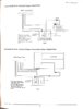
I'm trying to set up a Texecom Odysey X3 siren on a DSC PowerSeries PC1832 panel.
I can't work out the wiring from the panel to the siren.
The DSC has just two bell outputs:
Bell +
Bell -
The Texcom Odysey X3 has
+12v
Bell
Tmp
0v
Strb
Please can someone explain how I should connect these two up please?
I've a single siren, so assuming SAB is the correct setting.
I've discovered that the DSC can set a PGM output to be latching alarm output, so I can imagine I can use that for the strobe, so it continues to flash after an alarm where the bell has silenced.
Does anyone know how the Odysey's remote engineer hold off feature works? In future, if I am working on the panel and need to power it down, how will I prevent the siren from going off?
Thanks all, hopefully as few trips up the ladder tomorrow as possible! I'm replacing an old Group-4 bell box - with an actual ringing bell in it, old school.